効果的なプロトタイプの亜鉛ダイカストは、6 桁の金型の手戻りや製品発売の壊滅的な遅延に対する主な予防策です. エンジニアは、高価な部品を開発する前に部品設計を検証するという絶え間ないプレッシャーに直面しています。, 永久生産金型. 最終的な材料の性能を再現できないプロトタイピング方法を選択すると、多大な財務リスクが発生します, ハードツールの切断後に設計上の欠陥が発見されると、プロジェクト全体の予算とスケジュールが狂う可能性があるためです。.
このガイドは、プロトタイピング オプションを評価するための技術的なフレームワークを提供します。. コアメソッドを分析します, CNC 加工や重力鋳造から、試作用のソフト ツールまで. 亜鉛とアルミニウム合金の間の材料のトレードオフについても詳しく説明します, 亜鉛成分の DFM チェックリストを提供します, 各アプローチの重要なコストとタイムラインへの影響を詳細に説明し、設計が大量生産に対応できるようにします。.
亜鉛ダイカストの試作方法: CNCからソフトツーリングへ
適切な亜鉛プロトタイピング方法の選択は、機械的特性や表面仕上げなどの特定の設計特性に依存し、生産ツールに着手する前に検証が必要です。.
固体亜鉛バーストックからの CNC 機械加工
固体亜鉛バーストックから直接プロトタイプを機械加工することは、工具への投資を必要とせずに形状とフィット感を検証するための最も直接的な方法です。. この減算法により、最終部品の機械的特性をほぼ正確に近似することができます。, 急速な移動に最適です, 少量の検証サイクル. 単価が高い一方で、, 工具費用が完全に不要になります, 初期テストとフィードバック用に物理部品を迅速に入手する方法を提供します.
少量バッチ向けの石膏型鋳造
石膏型鋳造, ソフトツールの一種, SLA または CNC マスター パターンから作成された石膏またはゴム型を使用します. このアプローチにより、初期費用が大幅に削減されます, ツールへの投資は、多くの場合、約 10% 最終生産金型の. コスト効率の高い小ロットの製品に最適です。 50-100 単位. このプロセスにより、初期サンプルのテスト結果に基づいた迅速かつ安価な形状の修正も容易になります。, ハードツールが完成する前に設計を改良できるようにする.
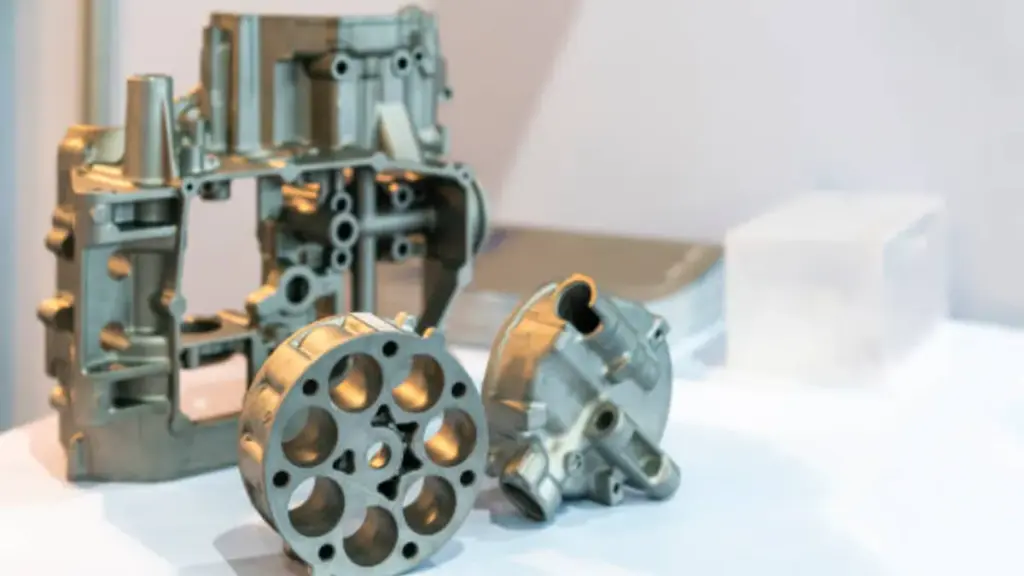
生産グレードの検証用の単一キャビティ ダイ
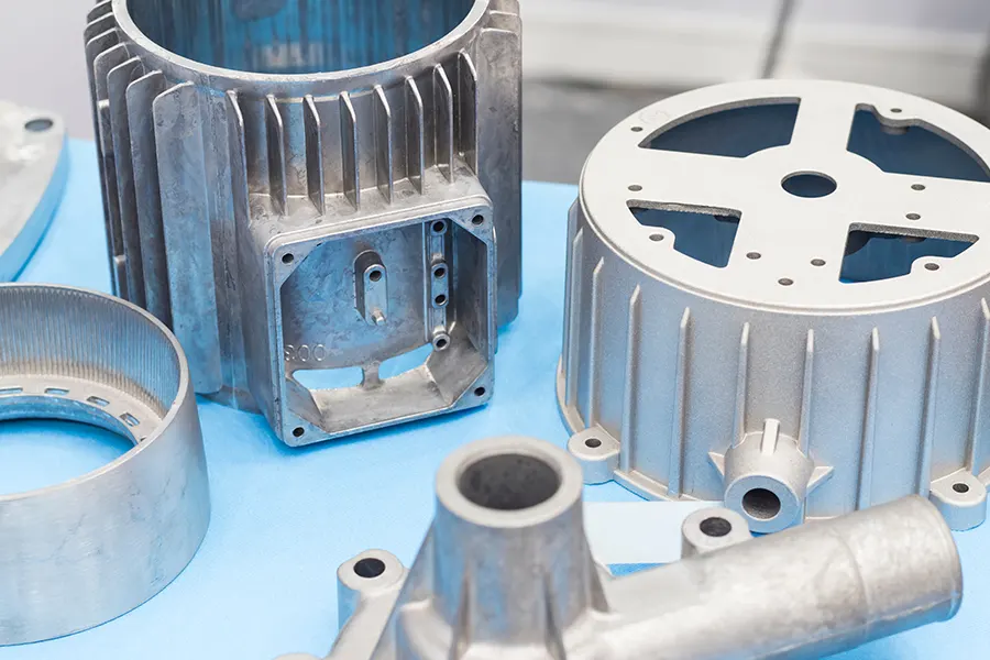
単一キャビティ金型の使用は、本格的な生産前に利用できる最も忠実度の高い評価方法です. このプロセスでは、同じ量産合金を使用するため、量産部品と同じ機械的特性と表面仕上げを備えたプロトタイプが作成されます。 (ザマックみたいに 3 または 5), 高圧, およびキャストパラメータ. パフォーマンスの最終的なテストとして機能します, 組み立て, そして美学, 検証された設計が、マルチキャビティ生産ツールに移行した後も期待どおりに動作することを保証します。.
材料の選択: 亜鉛ダイカスト vs アルミニウムダイカスト
亜鉛とアルミニウムのどちらを選択するかは、軽量化と、コンポーネントの高い衝撃強度とネット形状の複雑さの必要性との間の直接のトレードオフになります。.
機械的特性と重量対密度比
これらの材料の主な決定は、多くの場合、基本的な機械的要件に帰着します。. A380 のようなアルミニウム合金は、優れた強度重量比を実現し、密度は約 2.7 g/cm³, 自動車部品や大型電子筐体の軽量化のためのデフォルトの選択肢となっています。. コンポーネントの質量を減らすことが主なエンジニアリング目標である場合, アルミニウムは論理的な出発点です.
亜鉛合金, ザマックなど 3 そしてザマック 5, 約で大幅に密度が高くなります 5.0 g/cm3 で、アルミニウム鋳造品の 2 倍以上の強度があります。. これにより、より高い衝撃強度と優れた振動減衰特性が得られます。. 亜鉛は耐久性が要求される用途に適しています。, 構造的完全性, 複雑なキャストの能力, 二次加工を最小限に抑えたネットシェイプ部品.
熱伝導率と電気的性能
アルミニウムの優れた熱伝導性により、放熱の業界標準となっています. 高出力 LED 屋外照明ハウジングや新エネルギー車などの用途における熱管理に最適な素材です。 (NEV) パワートレインコンポーネント. 熱を効率的に伝達する材料の能力は、電子アセンブリの性能と寿命にとって非常に重要です。.
どちらの材料も、敏感な電子機器に効果的な EMI シールドを提供します。. 亜鉛の固有の特性, しかし, 高周波アプリケーションでパフォーマンスの優位性を提供できる, 信号の完全性が最優先される 5G 通信エンクロージャの有力な候補となる. 材料の選択は、製品の熱管理戦略全体に直接影響します。.
表面仕上げオプションと耐食性
仕上げ要件が大きな差別化要因となる. 亜鉛は高品質の装飾めっきおよび保護めっきに非常に適しています。, クロムを含む, ニッケル, そしてサテン仕上げ. 鋳造のままの表面は本質的にアルミニウムよりも滑らかです, これにより、多くの場合、仕上げ前の二次研磨ステップの必要性が軽減または排除されます。.
陽極酸化処理の選択肢はアルミニウムのみです, 硬い物質を作り出す電気化学プロセス, 耐食性, 装飾的な酸化物層も多くあります. この仕上げは部品自体と一体化しているため、亜鉛には適用できません。. アルミニウムは本来より高い耐食性を持っていますが、, 両方の材料の性能は、不動態化や粉体塗装などのプロセスによってさらに強化できます。, 最終的な性能は通常、標準化された塩水噴霧試験によって検証されています.
あなたのワンストップIATF 16949 ダイカストパートナー
の “マテリアルギャップ”: ザマックのシミュレーション 3 重力キャストによるパフォーマンス
重力鋳造プロトタイプは、迅速な, 部品の形状を検証するための低コストの方法, しかし、製品のダイカストとの固有の材料ギャップにより、その性能データは方向性のみを示します。.
重力キャスト プロトタイピングの理論的根拠
重力キャスト プロトタイピングは、初期投資を大幅に削減することで、初期段階の設計検証に費用対効果の高いパスを提供します。. このメソッドのツール, 石膏型をよく使う, 通常、かかる費用はわずか約 10% 最終生産金型の. このアプローチにより開発サイクルが加速されます, 幾何学的評価と適合チェックのために最初の物理部品を提供します。 2-3 週. このプロセスは、迅速な設計変更にも対応します。, エンジニアは、高価なハードツールを使用する前に、簡単に調整できる SLA または CNC マスター パターンを使用してコンポーネントの形状を調整できるため、.
機械的特性の比較: 重力 vs. プレッシャー
エンジニアは、重力鋳造のプロトタイプは高圧ダイカストの機械的強度を再現していないことを認識する必要があります。. 重力プロセスには、同じ材料の固化と密度を達成するために必要な力がありません。, その結果、部品の延性と靭性が低下します. その結果, 最終生産部品と比較して、寸法公差が広くなり、精度が低下することが予想されます。. 石膏型の表面仕上げも大まかな近似値であり、生産ツールを使用したコンポーネントで達成できる品質とは一致しません。.
試作データを生産計画に橋渡し
重力鋳造プロトタイプからのデータを戦略的に使用して、量産への移行を知らせます. 主な価値は物理的な検証にあります, パフォーマンステストではない. 明確な計画により、最終部品の機能について誤った期待を抱かせることなく、プロトタイプの洞察が生産計画を正しく導くことができます。.
- 重力鋳造プロトタイプを使用して適合性を確認する, 形状, 意図したアセンブリ内の全体的な幾何学的完全性.
- 重要な領域を特定する, 合わせ面や精密穴など, 最終仕様を満たすには仕上げ加工が必要です.
- すべての機械的性能データを方向性のあるものとして扱う, 最終的な設計の検証には、実際の製造ツールから鋳造された部品が必要であることを理解する.
の “ソフトツーリング” 戦略: 試作と生産の橋渡し
ソフト ツールは、真のキャスト プロパティを使用して部品の形状と機能を検証します。, 大量生産で使用される硬化鋼の製造金型に必要な多額の投資のリスクを軽減します。.
少量の検証のための石膏型鋳造
石膏型鋳造, ゴムプラスチック金型鋳造とも呼ばれます (回転数), 完全な生産ツールを使用せずに機能的なプロトタイプを作成するための実証済みの方法です. このプロセスは、SLA または CNC 加工されたマスター パターンを使用して、再利用可能なシリコン ゴム鋳造ツールを作成することから始まります。. このアプローチにより、初期費用が大幅に削減されます, 初期工具投資はおよそ 1000 ドルに達します 10% 生産用鋼金型の. この方法はコストと速度が低いため、迅速かつ安価な形状変更が容易になります。, エンジニアリング チームが設計をハード ツールに固定する前に反復して改良できるようにする. 厳格な機能テストや早期市場参入のために、最大数千個の部品のバッチを生産するための実用的なソリューションです。.
迅速なパターンと金型作成のための積層造形
積層造形により新製品の導入が加速 (NPI) デジタル設計から最初の物理的な金属部品までのパスを短縮することでサイクルを短縮. 光造形 (SLA) モデルを使用して、圧力ダイカスト用の短納期 H-13 鋼金型を直接作成できます。. これにより、結果として得られるプロトタイプの熱的特性と機械的特性が、完全な生産工程で得られたものと一致することが保証されます。, 信頼性の高い検証用データの提供. 3D プリントされたプラスチック部品は、視覚的な評価とパッケージングの検証を実行するための安価な方法を提供します。, 性能評価には使用できません. 本当の価値は、付加技術を使用して、生産グレードの金属コンポーネントを迅速に提供する一時的なツールを構築することにあります。.
機械加工されたプロトタイプとのトレードオフの評価
ソフトツーリングとバーストックからの CNC 加工のどちらを選択するかは、完全に検証の目標によって決まります。. 鋳造プロセスをテストする, 一方、もう一方は原材料をテストします. 決定には、プロトタイプのコスト構造とエンジニアリング目標を明確に理解する必要があります。.
- パーツのプロパティ: ソフトツーリングは真の鋳造特性を持つ部品を製造します, 粒子構造と潜在的な気孔率を含む. 固体バーストックからの CNC 加工により、材料本来の強度が検証されますが、鋳造プロセス自体による影響は再現されません。.
- コスト構造: 機械加工には工具への投資は不要ですが、1 個あたりのコストが高くなります, 5 個未満の量に最適です. ソフトツールは少額の投資を必要としますが、数十から数千の部品に及ぶバッチの単位あたりのコストを大幅に削減します。.
- 表面仕上げ: 石膏型からの表面仕上げは、機械加工された表面よりも最終的なダイカスト部品の質感と外観をより正確に表現します。. これは、美観とシール面などの特定の機能要件の両方を検証するために重要です。.
製造用のデザイン (DFM) 亜鉛部品のチェックリスト
亜鉛部品の規律ある DFM レビューは、金型の手戻りを減らす最も直接的な方法です, 単位コストの管理, 市場投入までの時間を短縮する.
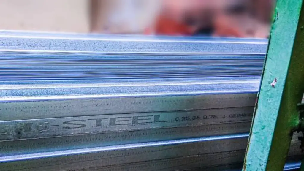
合金の選択と肉厚の均一性
DFM プロセスは材料の選択から始まります. ザマックなどの標準亜鉛合金の指定 3 またはザマック 5 一貫した材料特性と予測可能な性能を保証します, これは中国のグローバル拠点全体で製造する場合に重要です, メキシコ, またはベトナム. 部品の形状は合金の流動特性を補完する必要があります. 均一な肉厚の設計は、金型への完全な充填を促進するために不可欠です, 気孔などの欠陥の防止, 一貫した冷却速度を確保する. 厚さの急激な変化により応力集中が生じる. 鋳造中の溶融金属の流れと最終部品の構造強度の両方を向上させる, すべての内側と外側のコーナーに十分な半径を組み込んでいます. 鋭い内側の角により流れが妨げられ、荷重がかかると亀裂が入りやすい弱点が生じます。.
抜き勾配角度, 公差, および表面仕上げ
ダイカスト部品のすべてのフィーチャーは、製造しやすいように設計する必要があります. ダイの抜き方向と平行なすべての表面に抜き勾配を適用します。; コンポーネントやツールを損傷することなく部品を簡単に取り出すためには、これは譲れないことです。. 設計では現実的な寸法公差も定義する必要があります. 圧力ダイカストでは一般公差 ±0.1 mm を維持できますが、, これより厳しい仕様の場合は、二次的な CNC 加工が必要になることがよくあります, これにより、部品あたりのコストとリードタイムの両方が増加します. 図面に明確にマークを付けて、どの表面が表面であり、どの表面が純粋に機能的なものであるかを示します。. これにより、目標を絞った仕上げ作業が可能になります, コンポーネントの重要ではない領域での不必要なコストの防止.
設計検証のためのプロトタイピング パス
適切なプロトタイピング方法の選択は、検証の目標に完全に依存します。. 単一の完璧な方法はありません, 各パスは異なるコストバランスを示します, スピード, 最終的な制作部分への忠実性. 異なる方法で作成されたプロトタイプは、圧力ダイカスト生産部品と比較して、同一の機械的特性や表面仕上げを持ちません。.
- CNC加工: 固体亜鉛棒材から部品を機械加工することは、形状と適合性を検証する最も速い方法です. 工具への投資は必要ありませんが、部品あたりのコストが高く、鋳造部品の粒子構造や表面が再現されません。.
- シングルキャビティダイ: 真の機械的特性のテスト用, シングルキャビティのプロトタイプダイは、生産部品に最も近いものです。. 同じ生産合金と高圧プロセスを使用しています。, 厳密な機能テストに最適です.
- 石膏型鋳造: この重力ベースの方法は、複雑な形状の部品を少量バッチで生産するためのコスト効率の高い方法を提供します。. 高価な生産ツールに着手する前に設計を反復するのに適しています。.
料金 & タイムライン分析: プロトタイピング vs.. 生産金型
適切なツール パスを選択すると、初期投資とユニットあたりのコストのバランスが取れます。, プロジェクトの収益性と市場投入までの時間に直接影響を与える.
工具タイプ別の初期投資の内訳
初期工具への投資は、ダイカスト プロジェクトにおける最も重要な財務上の決定です。. 完全生産金型, コストを最適化するために中国の施設で開発しています, 最大の資本支出を表す. 検証とブリッジ製作用, 石膏型のような柔らかいツールは参入障壁を低くします, およその投資で 10% 生産金型のコストの. CNC 加工により、工具への直接投資が完全に不要になります, コストは部品ごとに計算されるため、, 最初の形状とフィットのサンプルに最適です. 中間地点を占める, 単一キャビティのプロトタイプ ダイには適度な投資が必要ですが、最終生産ユニットとほぼ同じ機械的特性を備えた部品が得られます。.
生産量全体にわたる単位当たりのコストの分析
ユニットあたりのコストは初期工具投資に反比例します。. 生産金型は最低のユニットあたりのコストを実現します, これらが大量生産の唯一の実行可能な選択肢になります。 3,000 単位以上, 高額な工具費用が効果的に償却される場合. ソフトツーリング, 石膏型鋳造など, 数千ユニットまでの短期またはブリッジ生産の場合、費用対効果が高くなります。. 単一キャビティのプロトタイプ ダイは適度なユニットあたりのコストを提供します, 高価なマルチキャビティツーリングを使用する前に、重要な部品の特性を検証するのに役立ちます. CNC 加工は、単位あたりのコストが大幅に高くなります。, 物理的なレビューのためのいくつかの初期サンプルを超えるものには実用的ではありません.
プロジェクトのタイムライン: デザインの最終決定から最初のパーツまで
最初の部分を受け取るまでのタイムラインは、選択した方法によって大幅に異なります. 当社の中国施設で製造される完全な生産金型には、 25-35 最初の商品検査までの工具の日数 (FAI) 発生する可能性があります. プロトタイピング方法により納期が大幅に短縮されます.
- CNC 加工されたプロトタイプ: 最速のオプション, CAD ファイルの提出から数日以内に物理部品を納品します.
- 石膏型の試作: 初期鋳造部品を短期間で納品します 2-3 週の時間枠.
- ラピッドダイカスト (SLA パターン): 初期サンプルを生成します 5-8 週, 部品の幾何学的複雑さの影響を受ける.
設計変更: 柔軟性とコストへの影響
設計を変更できることは開発中の重要な要素です. 硬化鋼の製造金型の修正は複雑です, 高価な, 時間のかかるプロセスにより、プロジェクトに大幅な遅れが生じる可能性があります. 対照的に, 石膏やシリコンなどの材料で作られた柔らかいツールにより、部品の形状を迅速かつ安価に調整できます。, 反復的な設計改良プロセスの促進. CNC 加工と 3D プリントにより最高度の柔軟性が得られます。; 設計の変更は、次の部品の実行に備えて CAD ファイル内で更新されるだけです, 変更するための物理的なツールが不要.
NPI ライフサイクルのための戦略的なツールの選択
新製品導入の成功 (NPI) 各フェーズで異なるツール戦略を使用してリスクとコストを管理する. この構造化されたアプローチにより、大量生産に着手する前に設計の検証が確実に行われます。.
- 構想段階: 最初の物理モデルに CNC 加工または 3D プリントを使用して、基本的な形状とフィット感を検証します。.
- 改良フェーズ: 頻繁な設計変更が予想され、迅速かつ手頃な価格で実装する必要がある反復的な機能テストにソフト ツールを採用します。.
- 実稼働前段階: 単一キャビティのプロトタイプ金型を使用して、生産レベルの機械的特性を備えた部品を製造します, スケーリング前の材料性能と表面仕上げ基準の確認.
- 量産段階: マルチキャビティへの取り組み, 大量生産向けの硬化鋼生産金型, その後、中国の当社施設に導入できます。, メキシコ, またはベトナムで特定の関税と物流目標を達成.
結論
亜鉛ダイカストの適切な試作方法を選択することが重要な最初のステップです. スピードの必要性のバランスをとることが重要です, 予算の制約, 最終設計が製造可能であることを保証するための材料の忠実度. よく計画されたプロトタイプ戦略は、生産ツールの成功に直接影響し、将来的にコストのかかる修正を削減します。.
新しい亜鉛成分を開発している場合, 当社のエンジニアリング チームは、予算とスケジュールに合わせた方法の選択をお手伝いします。. 明確な分析を提供して、試作から量産への移行をサポートします。.
よくある質問
亜鉛ダイカストの試作品の価格はいくらですか?
亜鉛ダイカストの試作品は工法によってコストが大きく変わります. CNC加工などの手法の場合, 初期のツール投資は不要です, ただし、1個あたりのコストが一般的に高い. あるいは, ソフトツーリング (石膏型鋳造) ツールのコストがおよそかかる、よりコスト効率の高いアプローチを提供します。 10% 最終生産金型の, 評価用の初期サンプルの作成に適しています。.
ダイカスト用ソフトツーリングとは?
ソフトツーリング, 石膏型鋳造またはゴムプラスチック鋳型鋳造としても知られています。 (回転数), 亜鉛の試作方法です, アルミニウム, およびマグネシウム合金. マスターパターンを使用します, 多くの場合、SLA または CNC を介して作成されます, 再利用可能なシリコンゴム鋳造工具を生産する. この重力ベースの鋳造プロセスにより、迅速かつ簡単な形状変更が容易になります。, 生産ツールに着手する前に設計を調整するのに最適です。.
ダイカストのサンプルを入手するのにどのくらい時間がかかりますか?
ダイカストサンプルの納期は試作方法によって異なります. 石膏型鋳造を使用 (ソフトツールの一種), 初期のプロトタイプは通常、 2 に 3 週. 光造形などの方法でパターンを作成するその他のラピッド プロトタイピング技術の場合 (SLA), サンプルの作成には 5 ~ 8 週間かかる場合があります, 部品の形状に応じて.
プロトタイプ部品は量産部品と同じくらい強度がありますか?
これは完全にプロトタイピング方法に依存します. 単一キャビティのプロトタイプ金型は、同一の合金とプロセスを使用するため、生産部品と同じ機械的特性を持つ鋳物を製造できます。. 対照的に, 亜鉛棒材から機械加工された部品は、機械的可能性の合理的な指標を提供します, 一方、3D プリントによるプロトタイプは性能評価には適していません。.