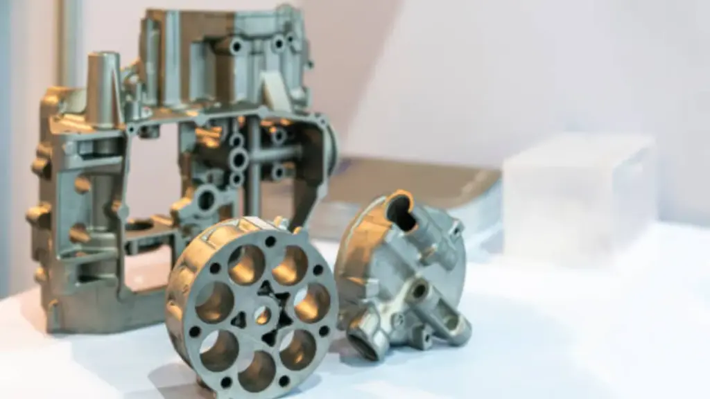
Consideraciones de diseño para carcasas de baterías para vehículos eléctricos
Carcasas para baterías de vehículos eléctricos (bandejas) son estructurales, Recintos relacionados con la seguridad que deben equilibrar la rigidez., resistencia a la intrusión por choque, confiabilidad del sellado, y capacidad de fabricación para producción de gran volumen. Para equipos de ingeniería y abastecimiento, la clave no es sólo "¿se puede lanzar?","Pero si el diseño puede cumplir consistentemente con la estabilidad dimensional, control de porosidad, y rendimiento de sellado después del mecanizado en producción en masa.
| Parámetro de ingeniería | Función crítica | Especificación típica |
|---|---|---|
| Integridad estructural | Resistencia al impacto de polo lateral | 5 Vigas transversales & Rieles de sección constante |
| Eficiencia masiva | Reducción de peso del sistema | ~20% de la masa total del sistema de batería |
| Rendimiento térmico | Difusión del calor & disipación | Conductividad ~120–235 W/m·K (Aleación de aluminio) |
| Tolerancia de fabricación | Planitud de la superficie de sellado | ±0,05 milímetros (Interfaces mecanizadas) |
Esta guía examina el proceso completo de diseño y fabricación de carcasas de fundición a presión., desde la selección de aleaciones de aluminio con conductividad térmica hasta 200 W/m·K para lograr IP67 Sellado mediante mecanizado de precisión.. Analizamos técnicas de producción específicas, incluyendo inyección asistida por vacío y circuitos de refrigeración integrados, que reducen las tasas de porosidad a menos 0.1% y garantizar la confiabilidad del sistema a largo plazo.
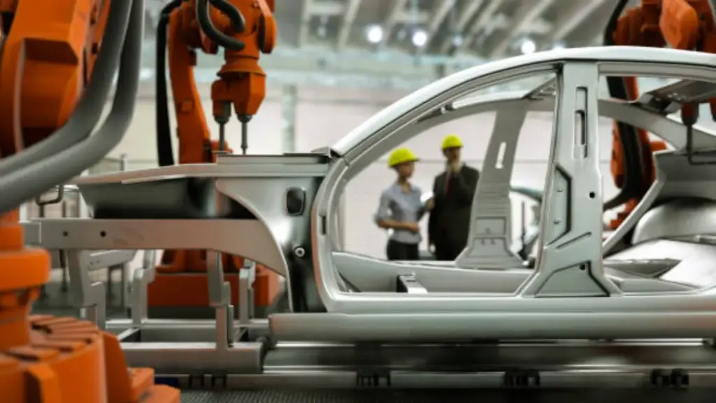
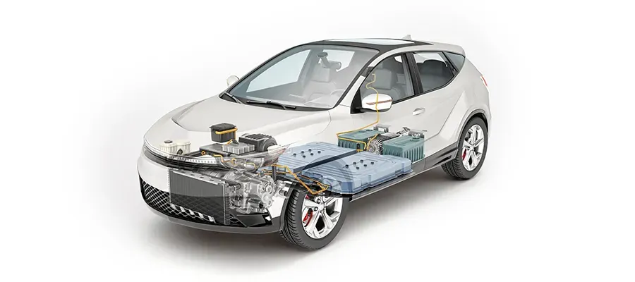
Arquitectura estructural y requisitos de seguridad
Una arquitectura práctica de bandeja de batería normalmente combina rieles perimetrales, travesaños, características locales de aplastamiento/impacto, e interfaces para módulos, enfriamiento, y cubre. El "mejor" diseño varía según los objetivos de la plataforma (rigidez, espacio de intrusión, estrategia de montaje), por lo que se deben realizar comprobaciones de capacidad de fabricación antes de congelar el diseño..
Desde el punto de vista de la fabricación, El rendimiento estructural y la confiabilidad del sello dependen en gran medida de cómo se reduce la porosidad., distorsión, y la consistencia de los datos están controlados. Bian Diecast Puede respaldar la revisión de viabilidad y la planificación de procesos, como el análisis de flujo del molde., Opciones de fundición a presión asistida por vacío para áreas sensibles a la porosidad., enderezar/remodelar pasos cuando sea necesario, y estrategia de referencia CNC, para que la pieza final pueda cumplir con los requisitos dimensionales y relacionados con fugas de manera consistente en la producción..
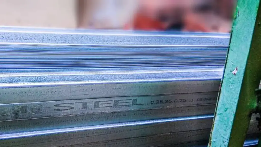
Optimización de materiales y compensaciones de peso
El aligeramiento es importante, pero para tren motriz/e-drive y piezas de carcasa, La elección de la aleación suele estar determinada por un conjunto combinado de limitaciones.: colabilidad para secciones delgadas, sensibilidad a la porosidad (especialmente para sellar), tolerancias de mecanizado requeridas, ambiente de corrosión, y necesidades de acabado de superficies.
Bian Diecast suele trabajar con aleaciones de fundición a presión de aluminio. (p.ej., ADC12 / Familias de Al-Si y otras variantes de Al-Si-Mg especificadas por el proyecto), y también puede admitir fundición a presión de zinc y magnesio para aplicaciones adecuadas. La selección final de la aleación debe confirmarse con la función de la pieza. (estructural versus. cubrir), necesidades de sellado, y procesos posteriores (CNC, recubrimiento en polvo/pintura, asamblea), y se puede optimizar durante la etapa DFM para reducir el riesgo y el costo en la producción en masa..
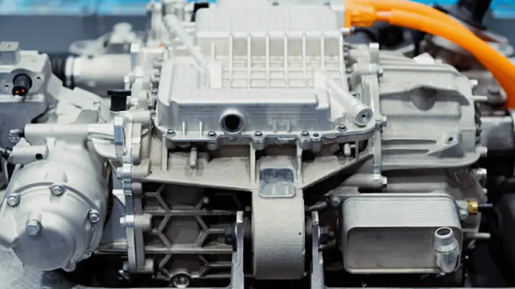
Selección de materiales para una conductividad térmica óptima
Para conducción eléctrica, inversor, y carcasas relacionadas con la batería, La fundición a presión de aluminio se selecciona ampliamente porque permite estructuras livianas con nervaduras/resaltes integrados y una distribución eficiente del calor, sin dejar de ser compatible con la fabricación de alto volumen.. El rendimiento térmico está influenciado por la química de la aleación., espesor de pared local, condición de la superficie, y qué tan bien la carcasa interactúa con la solución de enfriamiento (planos de contacto mecanizados, estrategia tim, y diseño de precarga del sujetador).
| Componente de gestión térmica | Especificación de materiales | Conductividad térmica (W/m · k) |
|---|---|---|
| Estructura de la vivienda (Fundido a presión) | Aleaciones Al-Si-Mg (p.ej., AlSi10Mg, ADC12) | 96 – 160 |
| Base de la placa de enfriamiento | Aluminio extruido (p.ej., 6Serie xxx) | 180 – 210 |
| Adhesivos estructurales | Poliuretano relleno / Epoxy | 1.5 – 2.8 |
| Rellenos de huecos (TIM) | Compuestos cargados de cerámica (80 % en peso de relleno) | 2.2 – 3.2 |
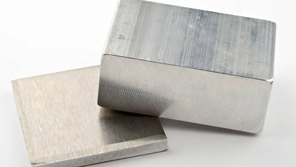
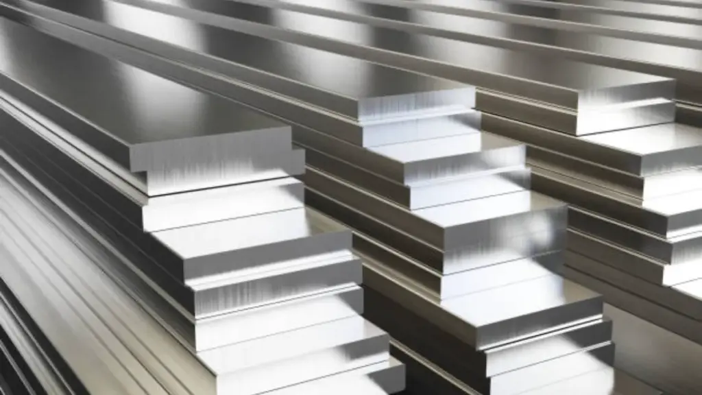
Propiedades de la aleación de aluminio y disipación de calor.
El aluminio sirve como principal disipador de calor en los paquetes de baterías modernos debido a sus propiedades térmicas favorables en comparación con los compuestos de acero o polímeros.. El aluminio puro establece el punto de referencia con una conductividad térmica total de aproximadamente 210 W/m · k. Mientras que elementos de aleación como silicio y el magnesio mejoran la moldeabilidad y la resistencia mecánica, reducen ligeramente esta conductividad. Aleaciones estructurales de fundición a presión., como A356, ADC12, o la serie 6xxx, normalmente conservan valores de conductividad que van desde 120 a 200 W/m · k, Dependiendo del estado de ánimo específico y la composición química..
Los ingenieros utilizan estos materiales para mantener las celdas de iones de litio dentro del margen operativo óptimo de 15 a 35 °C.. La carcasa de aluminio absorbe el calor generado durante los ciclos de carga rápida o descarga intensa y lo transfiere al sistema de refrigeración o al entorno externo.. Bian Diecasting equilibra las formulaciones de aleaciones para garantizar que la carcasa proporcione la rigidez estructural necesaria para la protección contra choques mientras actúa como un conducto térmico eficiente.. Esta doble funcionalidad elimina la necesidad de excesivos disipadores de calor secundarios., ahorro de peso y reducción de la complejidad del montaje.
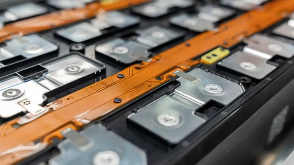
Materiales de interfaz térmica (TIM) y métricas de conductividad
Incluso con una carcasa de aluminio altamente conductora, Los espacios de aire microscópicos entre los módulos de batería y la placa de enfriamiento pueden crear una resistencia térmica significativa.. Materiales de interfaz térmica (TIM) eliminar estos cuellos de botella llenando los huecos con compuestos conductores. Los estándares actuales de la industria para adhesivos estructurales exigen una conductividad térmica mínima de 1.5 W/m · k. Los rellenadores de huecos avanzados ahora alcanzan con frecuencia entre 2,2 y 3,2 W/m·K, asegurando una rápida transferencia de calor desde la superficie de la celda a los canales de enfriamiento.
Lograr estos niveles de rendimiento a menudo requiere cargas de relleno de hasta 80 % en peso, utilizando materiales como el óxido de aluminio (Al₂O₃). Los fabricantes utilizan coadyuvantes de procesamiento para controlar la viscosidad., asegurar que el TIM se disperse uniformemente sin crear bolsas de aire. Actualización de un TIM desde un estándar 0.2 W/m·K a un alto rendimiento 2.2 La variante W/m·K reduce drásticamente la resistencia térmica. Las pruebas muestran que esta actualización puede reducir la temperatura de las celdas individuales entre 1 y 2 °C bajo carga, un margen crítico para prevenir la fuga térmica y extender la vida útil de la batería.
El proceso de fabricación de fundición a presión paso a paso
Fundición a presión de alta presión (HPDC) para carcasas de automóviles es un proceso repetible, pero el éxito depende del control de la estabilidad del llenado, desfogue, solidificación, y puntos de referencia de mecanizado posteriores. Un flujo de trabajo típico de producción en masa incluye: preparación de troquel → dosificación/inyección → llenado & intensificación → recorte/desbarbado → granallado/enderezado (si es necesario) → Mecanizado CNC → limpieza/secado → inspección → prueba de fugas (para piezas selladas) → recubrimiento/pintura/recubrimiento en polvo → montaje & embalaje.
Desde la preparación del troquel hasta la inyección a alta presión
Fundición a presión de alta presión (HPDC) inicia con la preparación precisa del molde. Los fabricantes sujetan matrices de dos partes., típicamente mecanizado a partir de acero para herramientas H13, usando una fuerza de bloqueo sustancial para soportar las presiones internas generadas durante el disparo. Para mitigar el choque térmico y evitar que el aluminio se suelde al acero., las superficies de la matriz se precalientan hasta una ventana operativa de 150 a 250 °C. Los sistemas automatizados aplican un spray lubricante durante 1 a 5 segundos entre ciclos., Creando una barrera que protege la cara del dado y ayuda en la eliminación del calor..
Después de la preparación, Comienza la secuencia de dosificación e inyección de metal.. Una cuchara robótica vierte un volumen específico de aleación fundida de Al-Si-Mg, como AlSi10Mg, en la manga de perdigones de una máquina de cámara fría. Un émbolo hidráulico acelera rápidamente, Forzar el metal fundido hacia la cavidad del troquel.. Esta fase de inyección ocurre en solo 0,02 a 0,2 segundos., una velocidad necesaria para llenar carcasas de baterías de paredes delgadas y geometrías complejas antes de que el metal pierda fluidez.
Solidificación, Expulsión, y gestión del ciclo
Mientras el metal se enfría, la máquina entra en una fase de intensificación, manteniendo presiones hidráulicas de 10 a 175 MPa (aproximadamente 1.450 a 25.000 psi) en la fundición solidificada. Esta presión sostenida comprime las inclusiones de gas y compensa la contracción volumétrica., asegurando una alta densidad del material e integridad estructural. Los canales de enfriamiento internos diseñados en el acero del troquel disipan activamente el calor., controlar la tasa de solidificación para refinar la microestructura y proteger la herramienta de la fatiga térmica.
El ciclo del proceso concluye cuando el componente alcanza un estado rígido adecuado para su remoción.. Los pasadores eyectores se extienden para empujar la pieza fundida fuera del molde., toda la secuencia, desde la sujeción hasta la expulsión, suele tardar entre 20 y 60 segundos. piezas estructurales automotrices. los expulsados “disparo,” que comprende la carcasa de la batería, corredores, y se desborda, pasa a una prensa de recorte donde se elimina el exceso de material antes de que la pieza ingrese a los flujos de trabajo de mecanizado CNC o tratamiento de superficies posteriores..
Diseñado para la precisión. Construido para escalar.
Lograr el sellado IP67 mediante fabricación de precisión
Protección de ingreso (p.ej., IP67 según IEC 60529) Se logra combinando una geometría que facilita el sellado con una fabricación y verificación controladas.. Las estrategias de diseño típicas incluyen ranuras para juntas., costillas entrelazadas, y conceptos de juntas que minimizan las rutas directas de fuga y, al mismo tiempo, dejan suficiente margen de mecanizado en las interfaces de sellado..
Del lado de la fabricación, La confiabilidad del sellado generalmente depende de tres controles vinculados.:
(1) Gestión del riesgo de porosidad durante la fundición. (a menudo respaldado por simulación y procesos asistidos por vacío para piezas críticas)
(2) Mecanizado CNC de planos de sellado y puntos de referencia para cumplir con los requisitos de planitud/rugosidad especificados por el cliente., y
(3) prueba de fugas (Métodos de caída de presión/vacío según sea necesario) validar cada lote de producción o 100% regiones, dependiendo del plan de calidad del programa. Este "elenco + máquina + El bucle de verificación es una capacidad clave para automotor Carcasas donde la estanqueidad y la estabilidad dimensional deben mantenerse constantes durante largos ciclos de producción..
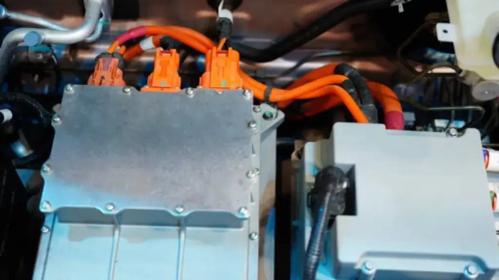
Integración de sistemas de enfriamiento durante la fundición
Para carcasas relacionadas con la gestión térmica, La integración de la refrigeración se puede lograr de diferentes maneras dependiendo del riesgo y los objetivos de costos.: costillas fundidas y funciones de difusión del calor, Planos de interfaz mecanizados para placas frías., o pasajes integrados e interfaces listas para ensamblar. El mejor enfoque debe evaluarse junto con los requisitos de sellado., utilidad, y cómo se ensamblará el sistema (sujetadores, adhesivos, tim, y tolerancias).
Regulación térmica del molde y diseño de canales.
El funcionamiento óptimo del troquel requiere mantener la temperatura del molde entre 180 y 250 °C utilizando sistemas de aceite caliente o agua a presión.. Los ingenieros diseñan canales de enfriamiento para que se encuentren entre 8 y 12 mm por debajo de la superficie de la cavidad con un diámetro de al menos 8 milímetros, Asegurar una extracción de calor eficiente durante la ventana de solidificación.. Esta geometría específica equilibra la necesidad de una rápida eliminación del calor con la resistencia mecánica necesaria para soportar el acero del troquel bajo fuerzas de sujeción..
Unidades avanzadas de control de temperatura (TCU) lograr una precisión de ±1°C para estabilizar las condiciones del proceso. Estos sistemas utilizan monitoreo multizona que activa alarmas si las diferencias de temperatura regionales superan los 5 °C., evitando la solidificación desigual. Para geometrías complejas con puntos de acceso distintos, Los fabricantes emplean redes de refrigeración de circuitos múltiples y tecnologías de refrigeración puntual., como jetPulse. Estos métodos de enfriamiento específicos gestionan activamente las áreas de alto calor para reducir los tiempos de ciclo y mitigar los riesgos de soldadura sin comprometer el equilibrio térmico de toda la herramienta..
Circuitos de enfriamiento integrados moldeados in situ
Los avances recientes en la fundición a presión a alta presión permiten incrustar tubos de aluminio EN AW-6063 o EN AW-3003 directamente en la carcasa.. Esta técnica crea un componente monolítico con rutas de enfriamiento internas., normalmente usando 12 tubos de mm de diámetro exterior. Eliminando la necesidad de placas de refrigeración externas, Este enfoque reduce significativamente los riesgos de fugas y mejora la conductancia térmica desde las celdas de la batería hasta el medio refrigerante..
Los equipos de producción deben calibrar los parámetros del proceso específicamente para proteger los tubos insertados contra el colapso.. Las presiones de fundición generalmente oscilan entre 600 y 1200 bar con velocidades de pistón limitadas a 2,5-4,5 m/s. Para garantizar aún más la estabilidad, Los operadores precalientan los tubos de inserción a 200°C.. Este paso de precalentamiento minimiza el choque térmico cuando los tubos entran en contacto con el aluminio fundido., que alcanza su punto máximo alrededor de 530°C, asegurando una unión metalúrgica robusta y una geometría de trayectoria de flujo consistente.
Postprocesamiento: Mecanizado CNC para sellar superficies
Las superficies fundidas rara vez cumplen directamente con los requisitos de sellado, por lo que el mecanizado CNC generalmente se aplica a interfaces funcionales como bridas de cubierta, ranuras de junta, Tierras de junta tórica, asientos de rodamiento/localizador, y características roscadas. El objetivo del mecanizado es ofrecer datos de referencia estables., planitud controlada, y un acabado superficial que coincida con la estrategia de sellado y el método de validación del cliente./
Con amplia capacidad CNC e inspección interna (p.ej., CMM y herramientas de medición dimensional), Bian Diecasting puede ejecutar “casting + mecanizado de precisión + verificación” como un proceso controlado, Reducir las transferencias de proveedores que a menudo introducen variaciones.. Después del mecanizado, La limpieza/secado y las pruebas de fugas se pueden integrar en el flujo de producción de carcasas con sellos críticos para reducir el riesgo de fallas en las últimas etapas del ensamblaje del cliente..
Control de calidad en la producción de viviendas para vehículos eléctricos
El control de calidad de las carcasas de las baterías de los vehículos eléctricos combina una estricta gestión medioambiental con pruebas físicas automatizadas.. Las líneas de producción utilizan ISO 14644-1 salas limpias (Clase 7-8) para minimizar la contaminación, mientras que la integridad estructural se verifica mediante inspección de soldadura láser 3D y pruebas de fugas de presión al final de la línea para garantizar el sellado IP67..
YO ASI 14644 Estándares de salas limpias y control de la contaminación
Los entornos de fabricación de componentes de baterías para vehículos eléctricos deben cumplir estrictos protocolos de limpieza para evitar la contaminación microscópica que podría comprometer la seguridad de las celdas o el aislamiento eléctrico.. Las instalaciones de producción implementan ISO 14644-1 estándares, normalmente asignando clase ISO 7 o clase 8 entornos para el montaje general de viviendas y la integración de paquetes. Procesos upstream más sensibles, como la fabricación de células o el apilamiento de módulos, a menudo requieren clase ISO 5 o clase 6 zonas, donde los límites de partículas se aplican estrictamente a ≤3520 partículas (≥0,5 µm) por metro cúbico.
Más allá del control de partículas, La regulación de la humedad es fundamental para proteger las sustancias químicas de iones de litio de la degradación inducida por la humedad.. Se integran salas secas con humedad ultrabaja en la línea de montaje para mantener puntos de rocío estables durante el proceso de sellado.. Estos controles ambientales funcionan dentro de marcos más amplios de gestión de la calidad., como la IATF 16949. Protocolos de validación, incluida la calificación de instalación (coeficiente intelectual), Calificación operativa (OQ), y calificación de desempeño (PQ), Garantizar que todos los sistemas de sala limpia cumplan consistentemente con las especificaciones de ingeniería requeridas para la seguridad de las baterías de grado automotriz..
Inspección de soldadura automatizada y prueba de fugas al final de la línea
La integridad estructural y el rendimiento del sellado dependen de métodos de verificación de alta precisión aplicados a cada unidad que sale de la línea.. Las carcasas de las baterías suelen contener más 150 Cordones de soldadura individuales que requieren 100% inspección. Los sistemas de visión automatizados que emplean triangulación láser 3D escanean estas costuras en tiempo real para detectar defectos microscópicos., porosidad, o desviaciones geométricas que podrían provocar fallas estructurales bajo cargas G del vehículo..
Para garantizar que el gabinete cumpla con los estándares de protección de ingreso IP67, Los fabricantes exigen pruebas de caída de presión al final de la línea.. Este proceso presuriza la carcasa con aire o gas trazador y monitorea la pérdida de presión durante un tiempo de permanencia establecido para identificar rutas de fuga.. Ensayos no destructivos complementarios, como la detección de defectos por rayos X y la máquina de medición de coordenadas (MMC) análisis, verifica la densidad interna de la fundición y la precisión dimensional. Estos rigurosos controles garantizan que la carcasa pueda soportar diferencias de presión interna y factores estresantes ambientales externos durante todo el ciclo de vida del vehículo..
Estudio de caso: Un nivel 1 Carcasa de batería del proveedor
Un desafío común para la conducción eléctrica / inversor / Las carcasas selladas equilibran la complejidad de las paredes delgadas con el control de la porosidad y datos de mecanizado estables.. En proyectos típicos de mejora., Es posible que los problemas solo aparezcan en la etapa final, como fallas en las pruebas de fugas después de que ya se haya agregado un valor de mecanizado significativo, lo que genera riesgos de desperdicio y cronograma..
Una ruta de mitigación comprobada es avanzar en la “prevención de defectos”: Utilice el análisis de flujo del molde para identificar riesgos de turbulencia y atrapamiento de aire., optimizar el diseño de compuertas/desbordamiento/ventilación, y evaluar la fundición a presión asistida por vacío para zonas sensibles a la porosidad. Río abajo, combinar inspección por rayos X (como lo requiere el programa), Medición CMM para estabilidad de referencia, y pruebas de fugas para cerrar el ciclo, de modo que los ajustes del proceso se verifiquen rápidamente y la producción pueda alcanzar un nivel estable., rendimiento repetible para suministro a largo plazo.
Pensamientos finales
La creación de carcasas eficaces para baterías de vehículos eléctricos exige un equilibrio preciso entre refuerzo estructural y reducción de masa.. La fundición a alta presión permite a los ingenieros producir componentes monolíticos de aluminio que integran perfectamente la protección contra choques con canales de gestión térmica.. Optimizando la selección de aleaciones y utilizando simulación de topología avanzada, Los fabricantes logran la resistencia mecánica necesaria para soportar impactos de polos laterales sin comprometer el alcance del vehículo o la dinámica del chasis..
En última instancia, la confiabilidad surge de un riguroso control y validación del proceso.. Lograr un sellado IP67 constante requiere algo más que un diseño robusto; Requiere un mecanizado CNC exacto de las superficies de contacto y pruebas automatizadas de caída de presión para garantizar la integridad hermética.. A medida que evolucionan las arquitecturas de los vehículos eléctricos, La capacidad de ejecutar estos complejos flujos de trabajo de fabricación distingue a los productos duraderos., sistemas de baterías de alto rendimiento de aquellos propensos a fallas ambientales prematuras.
Preguntas frecuentes
¿Cuál es la mejor aleación de aluminio para carcasas de baterías de vehículos eléctricos??
Aleaciones de aluminio fundido con alto contenido de silicio como A390 (AlSi17Cu4.5Mg) Se seleccionan con frecuencia por sus relaciones superiores de dureza a peso.. Para paneles estructurales inferiores, aleaciones de alta resistencia de la serie 6000, como 6111 en el pico de la edad también son comunes, ofreciendo aproximadamente 30% Ahorro de peso en comparación con el estándar AA5754-O..
¿Cómo se valida la resistencia a fugas de los paquetes de baterías fundidas a presión??
Para lograr la protección de ingreso IP67–IP69K, Las carcasas se someten a pruebas de fugas de gas trazador con límites estrictos., normalmente bajo 15 sccm para cerramientos principales y inferiores. 5 sccm para fundas. Los fabricantes también deben controlar la porosidad interna por debajo 0.1% durante el proceso de fundición para garantizar la integridad hermética.
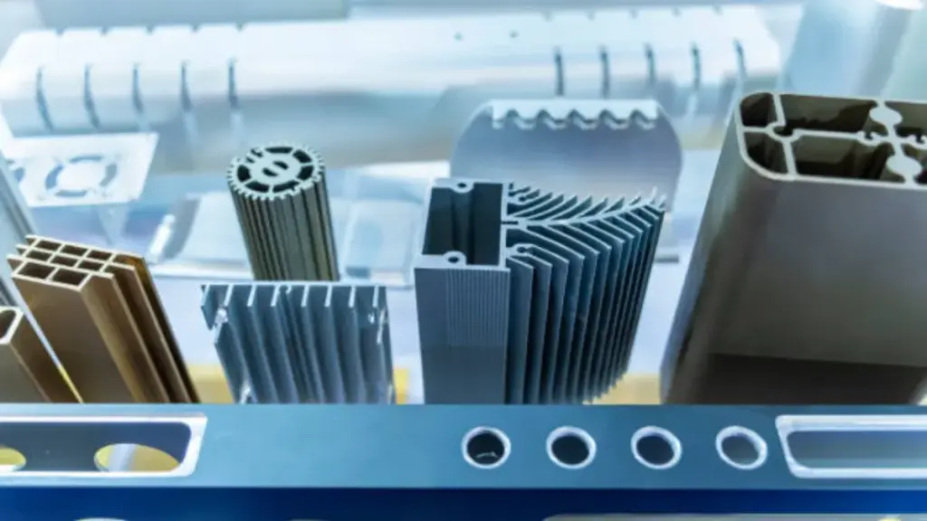
¿Cuándo se prefiere la fundición a presión a la extrusión para carcasas de vehículos eléctricos??
La fundición a presión es la opción dominante para geometrías complejas que requieren canales de refrigeración integrados., jefes, y cajas de bornes en un solo disparo. La extrusión generalmente se reserva para aplicaciones más simples., diseños de sección transversal constante donde se prioriza una mayor resistencia del perfil y menores costos de herramientas.
¿Cuál es el espesor de pared típico de las bandejas de baterías de aluminio??
La mayoría de las bandejas de baterías de aluminio tienen un espesor de pared entre 1.0 mm y 3.0 milímetros. Sin embargo, Las áreas estructurales y los puntos de montaje a menudo aumentan este espesor a 10-12 mm para soportar cargas mecánicas y garantizar una rigidez suficiente..
¿Cuál es el costo esperado para un molde de fundición a presión para carcasa de batería??
Para piezas estructurales a escala automotriz, un molde de acero dedicado normalmente cuesta entre $50,000 y $150,000. Estos moldes generalmente están diseñados para una vida útil de 80,000 a 100,000 tomas antes de requerir una renovación importante.
¿Cuál es la conductividad térmica del aluminio A380 para aplicaciones de refrigeración??
El aluminio A380 estándar de la industria ofrece una conductividad térmica de aproximadamente 96 W/m·K a temperatura ambiente. Este nivel es suficiente para muchas aplicaciones de gestión térmica., permitiendo que la propia carcasa ayude en la disipación del calor.