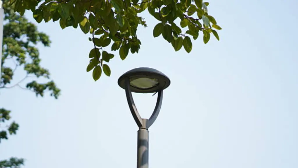
LED街路灯は高速道路で広く使用されています, 都市道路, 工業団地, 住宅コミュニティ, およびスマートシティプロジェクト. LED チップとドライバーが最も注目されることが多いですが、, 住宅も同様に重要です. 優れた設計のダイキャストハウジングが内部コンポーネントを保護, 効率的に熱を放散します, 過酷な屋外環境に耐える, 長期的な信頼性を保証します.
OEMブランド向け, 照明メーカー, と製品開発者, ハウジングの設計は生産コストに直接影響します, 熱性能, 組立効率, そして製品寿命. 不適切な設計決定は気孔率の欠陥につながる可能性があります, 過剰な体重, 過熱, 水漏れ, または高価なツールの変更.
このガイドでは、ダイキャスト LED 街路灯ハウジングを設計する際の重要な考慮事項と、性能と製造性の両方を最適化する方法について説明します。.
ダイカスト LED 街路灯ハウジングの基本
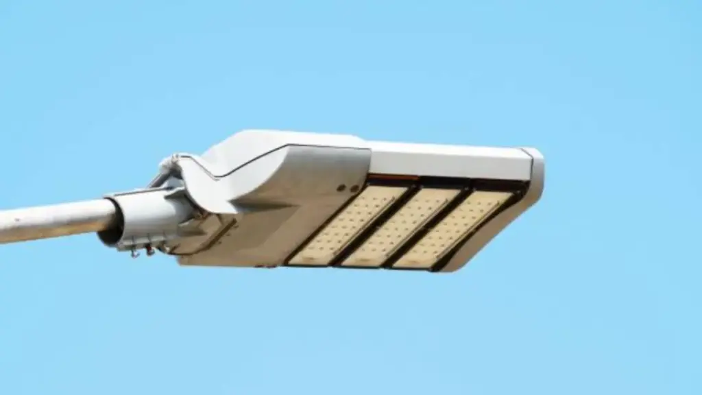
ダイカストアルミニウムハウジングは LED 街路灯の標準です. 機械的保護を兼ね備えています, 熱管理, 光学系の安定したベースを 1 つの量産部品に統合.
コア機能と要件
街路灯ハウジングは単なる箱ではありません. 長年にわたって確実に実行する必要がある 4 つの重要なジョブがあります, 天気の良い日に.
- 機械的保護: 光の内部を遮断します - LED モジュール, ドライバー, および配線 - 物理的な衝撃と振動から.
- 熱管理: ハウジング自体がヒートシンクとして機能します. 統合されたフィンとアルミニウムのボディが LED から熱を奪います。, これはパフォーマンスと寿命にとって非常に重要です.
- 環境に配慮したシーリング: ほこりや水が入らないようにする必要があります. IP65またはIP66の定格が標準です, 雨や嵐の中でもコンポーネントが乾いた状態に保たれるようにする.
- 構造的サポート: ハウジングは光学部品の剛性と正確な取り付け構造を提供します。, レンズ, そしてポールアタッチメント自体.
一般的な材料と特性
材料の選択は、最終的には熱性能の単純なバランスによって決まります。, 重さ, 耐食性. このアプリケーションの場合, 1つの素材が支配的.
- 主な材料: 定番はアルミダイキャスト製. ADC12 や A380 などの合金は、金型内でよく流動し、コスト効率が高いため、非常に一般的です。.
- 主要なプロパティ: 熱伝導率の高いアルミニウムが選ばれています, 良好な強度対重量比, 固有の耐腐食性.
- 表面仕上げ: ほとんどの場合、パウダーコート仕上げが適用されます. これにより、困難が追加されます, 耐候性を劇的に向上させる耐久性のある層, 紫外線への曝露, そして道路の汚れ.
主要な設計機能
優れたハウジング設計により、機能が鋳物に直接組み込まれます。, 部品数と潜在的な障害点を削減.
- 一体型ヒートシンク: 外部のフィンとリブはハウジング本体に直接鋳造されており、空気にさらされる表面積を最大化します。, それが自分自身を冷やす方法です.
- 内部コンパートメント: 内部はセパレートで設計されることが多い, ドライバーおよびその他の電子機器用の隔離されたコンパートメント, 涼しく整理整頓された状態に保つ.
- 正確な取り付けポイント: ネジボスや LED モジュールと光学系の位置合わせピンなどの機能が鋳造されています。, 組み立て中にすべてが完璧に揃っていることを確認する.
- 保守性: 最新の設計の多くには、メンテナンスを容易にする機能が含まれています, 工具不要のアクセス ラッチやヒンジ付きカバーなど, そのため、大きな困難を伴うことなくドライバーを交換できます.
ダイカスト製法のメリット
ダイキャストが使用されているのには理由があります. すべての構造要件を満たす部品を製造する最も効率的な方法です。, 熱, 街路灯の経済的ニーズ.
- 複雑な形状: このプロセスにより複雑な処理が可能になります, 肉厚が薄く、機械加工が困難または不可能な微細な部品を備えた一体部品.
- 高い一貫性: ツールが完成したら, 出てくるパーツはどれもほぼ同じです. これにより、数千のユニットにわたって高精度と寸法安定性が保証されます。.
- 強度と重量: 強いものを生み出します, 耐久性のある, それでいて軽量な筐体. これは、ポールの高いところに取り付けられ、風にさらされる部品にとって重要です。.
- 熱の統合: 最大の利点は、ヒートシンクがボルトで固定された別個の部品ではないことです。; 住宅構造の不可欠なコンポーネントです, 熱が逃げる直接的かつ効率的な経路を作成します。.
LED 街路灯のハウジング設計の優先事項
熱を逃がす堅牢な筐体設計, 必要なところにだけ光を当てる, 電柱の上で何十年も生き延びる, 後で修正やアップグレードが簡単になります. それはバランスをとる行為です.
熱管理と耐久性
これは生存に関わることだ. 住宅が熱や天候に耐えられない場合, 他には何も関係ありません. 全体のデザインは、何十年にもわたってエネルギーを散逸させ、風雨に耐えることを中心に構築されています。.
- 筐体自体がヒートシンクです. LED とドライバーから熱を奪うには、フィンが組み込まれたダイキャスト アルミニウムを使用するのが標準的な方法です。.
- LED ジャンクション温度を低く保つことが重要です. 誤解してください, 照明器具が早期に故障すると、光出力が低下します。. 適切な熱管理により動作寿命が延びます 50,000 時間.
- 器具はしっかりと密閉する必要がある. IP65 定格は最低限のものです; IP66の方が良い. これは、電子機器への水や埃の侵入を防ぐ堅牢なガスケットを使用しています。.
- 仕上がりは見た目だけじゃない. 腐食を防ぐために、クロメート変換層の上に多段階の粉体塗装を施すことは交渉の余地がありません, 紫外線による劣化, そして塩水噴霧.
光学性能と光制御
フィクスチャが存続できるようになると、, その仕事は、光が行くべき場所に正確に光を当てることです。それ以外の場所には光を当てません。. これは精度と制御を意味します, 生の力だけではない.
- 目標は地面を照らすことです, 空ではない. ハウジングは、空光を排除し、すべてのルーメンをターゲット領域に集中させる完全なカットオフ光学系をサポートするように設計する必要があります。.
- 均一性が安全を生み出す. 優れたハウジングにより、光を均一に分配する光学系が可能になります, 極間の危険なダークスポットを取り除きます.
- 同じ通りは 2 つとありません. ハウジングは、さまざまな IES タイプの配光レンズに対応できる柔軟なプラットフォームである必要があります。 (タイプ II または III のように) 特定の道路幅やレイアウトに合わせて.
- まぶしさは大きな危険です. 設計では、ドライバーの視界を損なう可能性のある高角度の光を遮断する統合バイザーまたはシールドを考慮する必要があります。.
構造の完全性とポールの統合
ハウジングは、照明器具とインフラストラクチャの間の物理的なインターフェイスです。. 強くなければなりません, 取り付けが簡単, 環境からの絶え間ない物理的ストレスに耐えることができる.
- ポールにしっかりと取り付けられ、正しく狙いを定められなければなりません. スリップフィッターなどの調整可能な取り付けシステムは、標準ポールを取り付け、正確な傾き調整を可能にするために不可欠です。.
- 風は一定の力です. 流線型のハウジング形状により有効投影面積を削減 (EPA), ポールにかかる風荷重を軽減します.
- 固定具は丈夫である必要がありますが、過度に重すぎてはなりません. スマートなエンジニアリングにより、最適化された肉厚と内部リブを使用して、かさばらずに剛性の高い構造を作成します。, 設置がより簡単かつ安全に.
- 取り付け接続は重大な障害点です. 時間の経過とともに緩んだり亀裂が入ったりすることなく、風や交通による絶え間ない振動に耐えられる十分な堅牢性がなければなりません。.
保守性と将来性
街路灯は長期的な資産です. メンテナンスと将来のアップグレードが容易になるように設計することで、使い捨て製品と賢明な投資を区別します.
- 技術者は工具不要でアクセスできることを高く評価しています. 工具を必要としないラッチやドアにより、ポールの上部にあるドライバーやその他の内部コンポーネントのメンテナンスをより迅速かつ安全に行うことができます。.
- 使い捨ての器具を設計しないでください. モジュール式 LED エンジンとドライバーにより、ハウジング全体を交換することなく、故障した部品を簡単に交換したり、新しいテクノロジーにアップグレードしたりできます。.
- 次の計画を立てる. NEMA ソケットや Zhaga ソケットなどの標準化されたインターフェイスを統合することで、フォトセルの追加が簡単になります, モーションセンサー, または将来のスマートシティノード.
- 清潔な場所を清潔に保つ. 密閉された光学チャンバーからドライバーコンパートメントを分離することで、日常のサービス中の埃や湿気による汚染を防ぎます。.
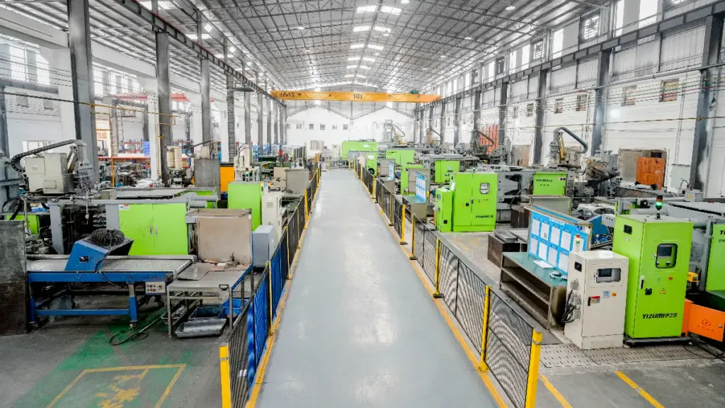
あなたのIATF 16949 認定ダイカストパートナー
肉厚と抜き勾配の設計
均一な肉厚と正しい抜き勾配のバランスをとることが重要です. これは部品の品質に直接影響します, 吐出信頼性, 工具寿命, そして最終的には, あなたの制作コスト.
鋳造品質を高めるために肉厚を最適化する
目指すのは強さだけではない; それは製造可能性です. ダイカストでは肉厚な部分が問題となります, 多孔性と長いサイクル時間につながる. 薄型を採用したスマートなデザイン, リブで補強された均一な壁により、生産上の悩みを引き起こすことなく作業を完了できます。.
- 均一な肉厚を維持する. メインハウジングシェル用, ターゲットは 2.5 ~ 4.5 mm であり、常にそれ以下に留まります 6 んん.
- シャープなトランジションではなく、フィレットと半径による緩やかなトランジションを使用します。, 厚さの急激な変化. これにより応力集中や空隙が防止されます。.
- リブと芯抜きセクションで強度を追加, 大きなものを作ることではなく, 金属の固体ブロックは部品の品質を低下させ、サイクル時間を延長します。.
- より薄く, 均一な壁がより早く冷える. これにより、合金の粒子構造がより微細になり、完成品の機械的特性が向上します。.
突き出しに正しい抜き勾配角度を適用する
適切なドラフトがない場合, あなたはただツールと戦っているだけです. パーツがきれいに外れません, 表面に傷が付く, エジェクターシステムに不必要なストレスがかかります. ドラフトが多いほど常に安全です, 特に内部の特徴とテクスチャーのある表面.
- 外壁のベースライン抜き勾配を 1.5 ~ 2° から始めます。. 内壁やポケットなどに, コアからのスムーズなリリースを確実にするために 2 ~ 3° を使用してください.
- より深いフィーチャーのために抜き勾配を増やす. 経験則としては、すべての角度にさらに 0.5 ~ 1° を追加することです。 25 深さ mm.
- テクスチャーのある表面では、擦り傷を防ぐためにより多くの抜き勾配が必要です. 軽いテクスチャーには 1 ~ 1.5° を追加する必要がある場合があります, 重いテクスチャにはさらに多くの量が必要です.
- 非常に低いドラフトを予約する, 0.5°くらい, 短い間だけ, 後加工ができない機能的に重要な表面. 正当化が必要なリスクです.
メタルフローと工具寿命を考慮した調整設計
CAD で見栄えの良い部品設計でも、生産現場ではツールが壊れる可能性があります. ドラフトの低い厚い壁により、大きな熱負荷と高い突出力が発生します。, 工具の早期故障につながります. 設計は、溶融金属が容易に流れ、抵抗なく放出できるようにする必要があります。.
- リブとフィンを使用して溶融合金をガイドします. これは完全な充填を確実にするのに役立ちます, 特に長いまたは複雑なハウジング形状の場合.
- 狭いデザインを避ける, 深い空洞. これらには、ダイス鋼に損傷または破損しやすい脆弱な形状を作成する必要があります。.
- 壁が厚く抜き勾配が不十分な設計では、工具に極度のストレスがかかります. この組み合わせにより、熱負荷と突き出し力が増加します, 動作寿命が短くなる.
- すべてのコーナーと接合部での大きな半径は交渉の余地がありません. 金属の流れを改善し、部品と金型自体の両方での応力集中を軽減します。.
シールやマウントなどの重要な機能の処理
IP 定格のシールや正確な光学的位置合わせなどの機能要件は、多くの場合、ダイカストのルールと衝突します。. 解決策は、まずプロセスを設計することです, 次に、ターゲットを絞った二次操作を使用して、必要に応じて最終仕様を達成します。.
- 可能な限り, 工具のパーティングライン上に平らなシール面を配置します。. これにより、その特定の領域でドラフトを行う必要がなくなります。.
- パーティング ライン上に配置できない重要な取り付け面またはシール面に対応, 小さいデザイン, 鋳造後に素早く平らに加工できる盛り上がったパッド.
- 嵌合部品の形状がドラフトに一致していることを確認してください. これにより、組み立て後に正しく組み合わせることができます, 各パートにドラフトがあるにもかかわらず.
- ドラフトの必要性と機能要件のバランスを常に保つ. IP 定格のシールと正確な光学的位置合わせ用, 後加工に頼る必要があるかもしれません.
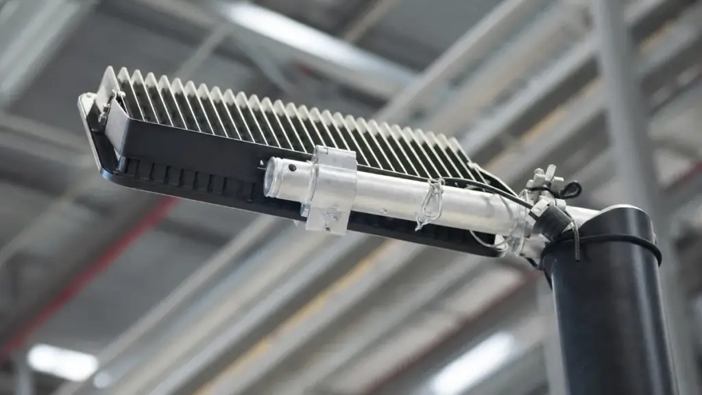
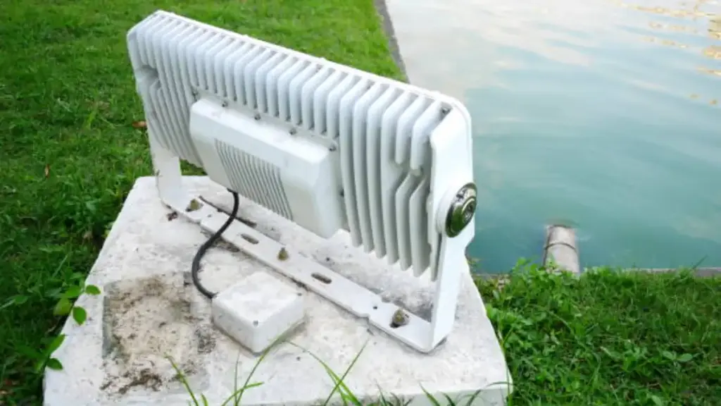
LED街路灯用ヒートシンク設計
ダイキャスト筐体全体がヒートシンク. その形状, 材料, 統合により照明器具の温度を直接制御, パフォーマンス, そして現実世界の寿命.
熱経路と材料の選択
主な目標は、途切れることのないものを生み出すことです。, LED 接合部から空気中に熱が逃げる低抵抗経路. 街路灯用, 標準はハウジング自体をヒートシンクとして使用することです, これが、ADC12 のようなダイキャストアルミニウムが頼りになる材料である理由です。. 内部, 高導電性アルミニウム PCB が必要です (MCPCB) 高品質のサーマルインターフェースマテリアル (TIM) LEDとハウジングの間のギャップを埋めるため. このチェーンに弱いリンクがあると、熱ボトルネックが発生します。, ジャンクション温度の急上昇を引き起こす. それは急速なルーメンの低下と早期故障に直接つながります.
フィンの形状と表面積の最適化
フィンをダイカストハウジングに直接組み込むことは、熱放散のための表面積を増やす最も効果的な方法です。. 自然対流冷却を最大限に高めるには、これらのフィンを自然の空気の流れ(通常は照明器具に沿って縦方向)に合わせる必要があります。. よくある間違いは、フィンの間隔が狭すぎることです. ほこりを防ぐために、それらの間隔は十分に広くする必要があります, 葉, 他のジャンクが蓄積して空気の流れを妨げるのを防ぎます. 非常に高出力の器具用, トポロジーに最適化された形状や統合された熱サイフォンなど、より複雑な設計を検討する必要がある場合があります。, しかし、ほとんどのアプリケーションでは, 適切に設計されたパッシブフィンで十分です.
パワーに合わせたサイジング, 気候, と寿命
ヒートシンクは、LED ジャンクション温度を 85°C 未満に保つのに十分な大きさである必要があります。, その場所の最悪の周囲条件下でも. これは、暑い気候向けの器具や、より高いワット数で動作する器具には、より広い表面積とより厚いフィンが必要であることを意味します。. いくつかの極端な環境では, LEDの電力を下げるのは理にかなっています. LED を最大容量より少し下で動作させると、温度が安定し、照明器具の耐用年数を大幅に延ばすことができます。. 太陽負荷も考慮する必要があります; 日中にハウジングに当たる直射日光により、システムが処理しなければならない大量の熱が追加されます。.
システム統合と設計検証
LED ドライバーは熱源でもあり、高温に敏感です。. コンポーネント間での熱の伝達を防ぐために、別のコンパートメントに置くか、外部に取り付けることで熱的に隔離する必要があります。. 適切なIP66シールが必要です, ただし、均圧ベントと組み合わせる必要があります. この通気孔により、器具が “息をする,” 電子機器やシールにストレスを与えることなく、内部の湿度と圧力の変化を管理します。. 工具を切る前に, 熱シミュレーション ソフトウェアを使用して熱流をモデル化し、鋳造形状を最適化します。. 物理的なプロトタイプを作成したら, 実際の負荷条件下でテストし、すべての重要なコンポーネントの温度を測定して、設計を検証する必要があります。.
シールおよび取り付け設計の詳細
ハウジングの密閉および取り付け設計により長期信頼性が保証されます. 目標は、IP/IK 評価を満たすことです, 圧力変化を管理する, 環境ストレスから器具を保護します.
保護と信頼性に関する中心的な目標
シールと取り付けに関するあらゆる設計上の決定は、長期的な屋外生存のためのいくつかの譲れない目標に遡ります。.
- IP66 または IP67 定格を達成し、内部電子機器を粉塵から保護します, 雨, そして高圧ウォータージェット.
- 破壊行為や環境上の危険に対する IK08 以上の衝撃評価を満たす機械的堅牢性を確保.
- 風荷重下でも照明器具の位置合わせと構造的完全性を維持, 振動, および熱サイクル.
- 製品の寿命にわたってシール性能を低下させることなく、ドライバーと光学系へのサービスアクセスを可能にします.
ガスケットシステムとシーリングインターフェース
ガスケットは主な防御線です. その材質と嵌合する表面は、偶然に任せることができない重要な設計ポイントです。.
- 継続的, クローズドループシリコンガスケットは高温に対する優れた耐性を提供します, 紫外線への曝露, 長期圧縮永久歪み.
- フラット, 連続的なシールランドはダイカストハウジングに直接設計されており、ガスケットの均一な圧縮を保証します。.
- 統合されたネジボスと圧縮リミッターが締めすぎを防止し、ガスケットの完全性を保護します.
- すべての重要なインターフェースは密閉されています, メインハウジングカバーを含む, 光学レンズアセンブリ, およびケーブルエントリーグランド.
均圧化と通気戦略
完全に密閉されたボックスは、温度が変化すると内部圧力が上昇します。, シールにストレスがかかり、結露が発生する. 適切な通気口により、水を侵入させずにこの問題を解決します.
- 疎水性膜呼吸バルブが組み込まれており、日々の温度変化によって生じる内部圧力を均一にします。.
- 液体の水を遮断しながら水蒸気を逃がすことで、光学コンパートメント内の結露や曇りを防ぎます。.
- 内部圧力の上昇や真空効果によって生じる可能性のあるガスケットやシールへの機械的ストレスを軽減します。.
- 通気口は、直接の水の飛沫や破片の蓄積から保護するように配置されています。.
統合された取り付けおよび調整機能
取り付けシステムを後付けでハウジングにボルトで固定することはできません. 鋳物に組み込むことで、照明器具を何十年も安全に保つのに必要な強度が得られます。.
- 取り付け機能, スピゴットエントリーやサイドアームブラケットインターフェースなど, 最大の強度を得るためにハウジングに直接鋳造されています.
- チルト調整機構を内蔵, 通常は許可します 5-10 水や雪をはじくのに役立つ度の角度.
- 鋸歯状の表面や止めネジなどの回転防止機能により、照明器具の狙いをしっかりと保ちます.
- 内部チャネルはケーブルを安全に配線します, 取り付け中に挟まれたり損傷したりするのを防ぎます.
環境耐久性を考慮した材質と仕上げ
アルミダイカストが基礎です, しかし、その寿命は留め具に依存します, コーティング, およびそれを使用するために選択されたケーブル.
- ステンレススチール製の留め具は腐食に強く、長年にわたり一貫した締め付け力を維持します。.
- 酸化や環境汚染物質から保護するために、ダイカストアルミニウムハウジングには耐久性のあるパウダーコート仕上げが施されています。.
- 柔軟なゴム製ジャケットを備えた低温定格ケーブルは、低温での亀裂を防止します, グランドでのシールの完全性を確保する.
- ガスケットの合わせ面には、潜在的な漏れ経路を形成する可能性のある鋳造気孔やバリが発生しないように保たれます。.
街路灯ハウジングに関する DFM ルール
街路灯ハウジングの効果的な DFM により材料選択のバランスが取れます, 壁の厚さ, 長期的な構造を確保するためのツール設計, 熱, 現場でのシール性能を向上.
| DFM カテゴリー | 重要な設計ルール |
|---|---|
| 構造および材料の DFM |
|
| 熱管理と放熱 |
|
| シーリングとコンポーネントのインターフェース |
|
| ツーリング, 公差, そして仕上げ |
|
よくある質問
LED街路灯ハウジングのダイカストとは何ですか?
ダイカストは、溶融したアルミニウムを高圧下で鋼の金型に注入する製造プロセスです。. LED街路灯用, これにより単一のものが作成されます, 筐体となる精密部品, ヒートシンク, すべての内部コンポーネントを保護するエンクロージャ.
LED街路灯ハウジングに最適なアルミニウム合金はどれですか?
A356-T6 は強度のバランスが取れているため、多くの場合、高性能ハウジングに最適な選択肢です。, 熱散逸, 耐食性. ADC12 は、よりコスト重視の用途に使用されるもう 1 つの一般的な合金です。, 優れた鋳造性により大量生産が可能.
ダイキャスト LED 街路灯用のヒートシンクはどのように設計されていますか?
ヒートシンクは通常、外部フィンとしてダイカストハウジングに直接組み込まれます。. この設計は、自然な空気対流によって熱を放散する表面積を最大化することに重点を置いています。, LEDからハウジングまでの明確な熱経路を維持, 熱に弱いドライバーを別のコンパートメントに保管.
これらのダイカスト部品に必要な抜き勾配はどれくらいですか?
抜き勾配角度, またはテーパー, 部品を金型から取り外すために必要です. 一般的な角度は、外壁の場合は 0.5° ~ 1°、内部ポケットの場合は 1° ~ 2° です。. ヒートシンク フィンなどの高いフィーチャでは、取り出し時の損傷を防ぐために 1° ~ 3° が必要になる場合があります.
アルミダイカストハウジングの厚さはどれくらいあるべきか?
ダイカストアルミニウム街路灯ハウジングの一般的な壁の厚さは、 1.5 mmと 3.5 んん. 絶対値よりも均一な厚みを維持することが重要. 壁を過度に厚くするのではなく、剛性を高めるためにリブを使用する必要があります。, 鋳造欠陥につながる可能性があります.
屋外街路灯の一般的な IP 定格はどのようなものですか?
屋外街路灯の標準定格はIP65です。, ハウジングを防塵にし、雨などの低圧水流に対して耐性を持たせる. 激しい嵐や高圧洗浄が行われる地域では, IP66 定格は、防水性を高めるためによく使用されます。.
なぜ製造可能性を考慮した設計なのか (DFM) ツールを作る前に重要?
ダイカスト工具は非常に高価で修正が難しいため、DFM は不可欠です. まず製造可能性を考慮して設計を分析することにより、, 一貫性のない壁厚や不十分な抜き勾配などの潜在的な問題を修正できます。. これにより、コストのかかるツールのやり直しが防止されます, 製造上の欠陥を減らす, 最終的なハウジングがすべての性能要件を満たしていることを保証します.
最終的な考え
街路灯ハウジングの設計は一連のトレードオフです, しかし信頼性は譲れない. 工具や壁の厚さをわずかに節約すると、現場で致命的な故障が発生する可能性があります, マージンを侵食し、ブランドの信頼性を破壊する. ここで説明する DFM 標準は、信頼できる資産と将来の負債の間のファイアウォールです。.
これらの原則を正しく実行するには、経験豊富な製造パートナーが必要です. 製品のパフォーマンスを偶然に任せないでください. 技術図面を確認するか、次の OEM 住宅プロジェクトを開始するには、当社のエンジニアリング チームにお問い合わせください。.