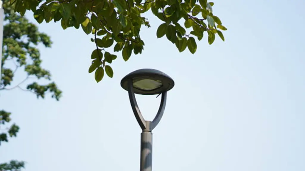
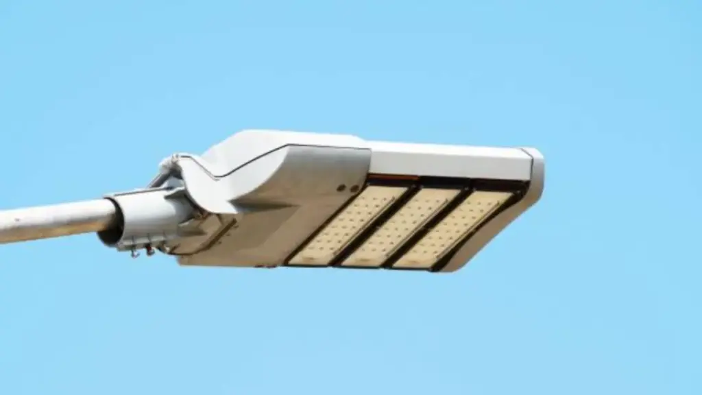
Las farolas LED se utilizan ampliamente en las carreteras, vías urbanas, parques industriales, comunidades residenciales, y proyectos de ciudades inteligentes. Si bien los chips y controladores LED suelen recibir la mayor atención, la vivienda es igualmente importante. Una carcasa de fundición a presión bien diseñada protege los componentes internos, disipa el calor eficientemente, Resiste ambientes exteriores hostiles., y garantiza confiabilidad a largo plazo.
Para marcas OEM, fabricantes de iluminación, y desarrolladores de productos, El diseño de la vivienda afecta directamente el costo de producción., rendimiento térmico, eficiencia de montaje, y vida útil del producto. Las malas decisiones de diseño pueden provocar defectos de porosidad, peso excesivo, calentamiento excesivo, fuga de agua, o modificaciones costosas de herramientas.
Esta guía explica las consideraciones clave al diseñar carcasas de farolas LED de fundición a presión y cómo optimizarlas tanto en términos de rendimiento como de capacidad de fabricación..
Conceptos básicos de la vivienda de alumbrado público LED fundido a presión
Las carcasas de aluminio fundido a presión son el estándar para las farolas LED. Combinan protección mecánica, gestión térmica, y una base estable para la óptica en una pieza producida en masa.
Funciones y requisitos principales
Una carcasa de alumbrado público no es sólo una caja. Tiene cuatro trabajos críticos que debe realizar de manera confiable durante años, afuera en el clima.
- Protección mecánica: Protege las entrañas de la luz: módulos LED, conductores, y cableado, por impacto físico y vibración.
- Gestión del calor: La propia carcasa actúa como disipador de calor.. Las aletas integradas y el cuerpo de aluminio alejan el calor de los LED, Lo cual es crucial para el rendimiento y la vida útil..
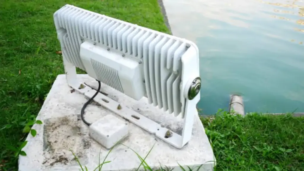
- Sellado ambiental: Debe mantener fuera el polvo y el agua.. Una clasificación de IP65 o IP66 es estándar, Garantizar que los componentes permanezcan secos durante la lluvia y las tormentas..
- Soporte estructural: La carcasa proporciona una estructura de montaje rígida y precisa para la óptica., lentes, y el propio accesorio del poste.
Materiales y propiedades comunes
La selección de materiales se reduce a un simple equilibrio de rendimiento térmico., peso, y resistencia a la corrosión. Para esta aplicación, un material domina.
- Material primario: La opción preferida es el aluminio fundido a presión.. Las aleaciones como ADC12 o A380 son extremadamente comunes porque fluyen bien en el molde y son rentables..
- Propiedades clave: El aluminio se elige por su alta conductividad térmica., buena relación fuerza-peso, y capacidad inherente para resistir la corrosión.
- Acabado de la superficie: Casi siempre se aplica un acabado de capa en polvo.. Esto añade un duro, capa duradera que mejora drásticamente la resistencia a la intemperie, exposición a los rayos ultravioleta, y suciedad del camino.
Características clave del diseño
El buen diseño de la carcasa integra la funcionalidad directamente en la pieza fundida., Reducir el número de piezas y los posibles puntos de fallo..
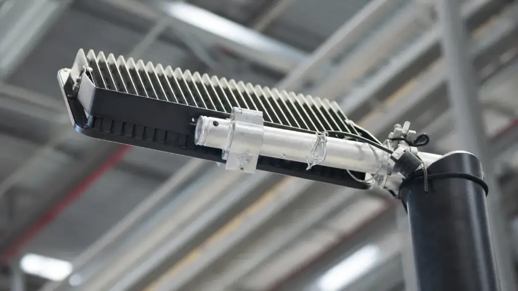
- Disipadores de calor integrados: Las aletas y nervaduras externas están fundidas directamente en el cuerpo de la carcasa para maximizar la superficie expuesta al aire., así es como se enfría.
- Compartimentos internos: El interior suele estar diseñado con, compartimentos aislados para el conductor y otros dispositivos electrónicos, mantenerlos más frescos y organizados.
- Puntos de montaje precisos: Características como salientes de tornillos y pasadores de alineación para los módulos LED y la óptica están moldeados, asegurando que todo se alinee perfectamente durante el montaje.
- Utilidad: Muchos diseños modernos incluyen características para un mantenimiento más sencillo., como pestillos de acceso sin herramientas o cubiertas con bisagras, para que los controladores se puedan cambiar sin mayor problema.
Ventajas del método de fundición a presión
La fundición a presión se utiliza por una razón.. Es la forma más eficiente de producir una pieza que cumpla con todos los requisitos estructurales., térmico, y necesidades económicas de una farola.
- Geometría compleja: El proceso permite intrincados, Piezas de una sola pieza con paredes delgadas y detalles finos que serían difíciles o imposibles de mecanizar..
- Alta consistencia: Una vez hecha la herramienta, cada parte que sale es casi idéntica. Esto garantiza una alta precisión y estabilidad dimensional en miles de unidades..
- Fuerza y peso: Produce fuertes, durable, carcasas aún ligeras. Esto es fundamental para las piezas que se montarán en lo alto de postes y se expondrán al viento..
- Integración Térmica: La mayor ventaja es que el disipador de calor no es una pieza separada atornillada.; Es un componente integral de la estructura de la vivienda., creando un camino directo y eficiente para que escape el calor.
Prioridades de diseño de viviendas de alumbrado público LED
Un diseño de carcasa sólido expulsa el calor, pone luz solo donde es necesario, sobrevive décadas en un poste, y facilita su reparación o actualización más adelante. Es un acto de equilibrio.
Gestión térmica y durabilidad
Esto se trata de supervivencia. Si una vivienda no puede soportar el calor y el clima, nada más importa. Todo el diseño se basa en disipar energía y resistir los elementos durante décadas..
- La propia carcasa es el disipador de calor.. El uso de aluminio fundido a presión con aletas integradas es la opción estándar para alejar el calor de los LED y el controlador..
- Mantener baja la temperatura de la unión del LED es todo el juego. hazlo mal, y la salida de luz cae mientras el dispositivo muere prematuramente. Una gestión térmica adecuada prolonga la vida operativa 50,000 horas.
- Los accesorios deben estar sellados herméticamente. Una clasificación IP65 es el mínimo indispensable; IP66 es mejor. Esto se basa en juntas robustas para mantener el agua y el polvo fuera de los componentes electrónicos..
- El acabado no es sólo para la apariencia.. Un recubrimiento en polvo de varias etapas sobre una capa de conversión de cromato no es negociable para combatir la corrosión., Degradación UV, y spray de sal.
Rendimiento óptico y control de luz
Una vez que el dispositivo pueda sobrevivir, su trabajo es poner la luz exactamente donde se supone que debe ir, y en ningún otro lugar. Esto significa precisión y control., no sólo potencia bruta.
- El objetivo es iluminar el suelo., no el cielo. La carcasa debe estar diseñada para admitir ópticas de corte total que eliminen el brillo del cielo y enfoquen cada lumen en el área objetivo..
- La uniformidad crea seguridad. Una buena carcasa permite ópticas que distribuyen la luz de manera uniforme, que elimina los peligrosos puntos oscuros entre los polos.
- No hay dos calles idénticas.. Una carcasa debe ser una plataforma flexible que se adapte a diferentes lentes de distribución tipo IES. (como tipo II o III) para coincidir con anchos y diseños de carreteras específicos.
- El deslumbramiento es un peligro importante. El diseño debe permitir viseras o protectores integrados para cortar la luz de ángulo alto que puede afectar la visión del conductor..
Integridad estructural e integración de polos
La vivienda es la interfaz física entre la luminaria y la infraestructura.. tiene que ser fuerte, fácil de instalar, y capaz de soportar el estrés físico constante del entorno.
- Debe fijarse al poste de forma segura y apuntar correctamente.. Los sistemas de montaje ajustables, como los deslizadores, son cruciales para instalar postes estándar y permitir ajustes de inclinación precisos..
- El viento es una fuerza constante.. La forma aerodinámica de la carcasa reduce el área proyectada efectiva (EPA), lo que reduce la carga de viento en el poste.
- Un elemento fijo debe ser resistente pero no excesivamente pesado.. La ingeniería inteligente utiliza espesores de pared optimizados y nervaduras internas para crear una estructura rígida sin volumen, haciendo la instalación más fácil y segura.
- La conexión de montaje es un punto crítico de falla. Debe ser lo suficientemente robusto para soportar la vibración constante del viento y del tráfico sin aflojarse ni agrietarse con el tiempo..
Facilidad de servicio y preparación para el futuro
Una farola es un activo a largo plazo. Diseñar para un fácil mantenimiento y futuras actualizaciones separa un producto desechable de una inversión inteligente.
- Los técnicos aprecian el acceso sin herramientas. Los pestillos o puertas que no requieren herramientas permiten un mantenimiento más rápido y seguro del conductor y otros componentes internos en la parte superior de un poste..
- No diseñes un accesorio desechable. Los motores y controladores LED modulares permiten el reemplazo simple de piezas defectuosas o actualizaciones a tecnología más nueva sin reemplazar toda la carcasa..
- Planifique lo que sigue. La integración de interfaces estandarizadas como enchufes NEMA o Zhaga facilita la adición de fotocélulas, sensores de movimiento, o nodos de ciudades inteligentes en el futuro.
- Mantenga limpias las áreas limpias. Separar el compartimiento del controlador de la cámara óptica sellada evita la contaminación por polvo o humedad durante el servicio de rutina..
Su IATF 16949 Socio certificado de fundición a presión
Diseño de espesor de pared y ángulo de tiro
Es esencial equilibrar el espesor uniforme de la pared con los ángulos de inclinación correctos.. Esto afecta directamente la calidad de la pieza., confiabilidad de la eyección, vida útil de la herramienta, y finalmente, sus costos de producción.
Optimización del espesor de pared para la calidad de la fundición
El objetivo no es sólo la fuerza; es capacidad de fabricación. Las secciones gruesas son un problema en la fundición a presión, provocando porosidad y tiempos de ciclo prolongados.. El diseño inteligente utiliza, Paredes uniformes reforzadas con nervaduras para realizar el trabajo sin crear dolores de cabeza en la producción..
- Mantener un espesor de pared uniforme. Para carcasas de carcasa principal, objetivo de 2,5 a 4,5 mm y manténgase siempre por debajo 6 milímetros.
- Utilice transiciones graduales con filetes y radios en lugar de nítidas., cambios bruscos de espesor. Esto evita concentraciones de tensiones y porosidad..
- Agregue fuerza con nervaduras y secciones sin núcleo, no creando grandes, Bloques sólidos de metal que degradan la calidad de las piezas y prolongan los tiempos de ciclo..
- Disolvente, las paredes uniformes se enfrían más rápido. Esto promueve una estructura de grano más fina en la aleación y da como resultado mejores propiedades mecánicas para la pieza terminada..
Aplicar ángulos de tiro correctos para la expulsión
Sin borrador adecuado, solo estás luchando contra la herramienta. La pieza no se suelta limpiamente, las superficies quedan marcadas, y pones tensión innecesaria en el sistema eyector. Más borrador siempre es más seguro, especialmente en elementos internos y superficies texturizadas.
- Comience con un ángulo de referencia de 1,5 a 2° para paredes externas.. Para paredes internas y bolsillos, use 2–3° para asegurar una liberación suave del núcleo.
- Aumente el borrador para funciones más profundas. Una buena regla general es agregar otros 0,5 a 1° por cada 25 mm de profundidad.
- Las superficies texturizadas necesitan más corriente de aire para evitar raspaduras. Una textura ligera puede requerir agregar entre 1 y 1,5°, y las texturas más pesadas necesitan aún más.
- Reserva calado muy bajo, como 0,5°, solo por corto, Superficies funcionalmente críticas donde el posmecanizado no es una opción.. Es un riesgo que necesita justificación..
Diseño coordinado para el flujo de metal y la vida útil de la herramienta
Un diseño de pieza que se ve bien en CAD puede destruir una herramienta en producción. Las paredes gruesas con bajo tiro crean cargas térmicas masivas y altas fuerzas de expulsión., lo que conduce a un fallo prematuro de la herramienta. El diseño debe ayudar a que el metal fundido fluya fácilmente y se libere sin luchar..
- Utilice nervaduras y aletas para guiar la aleación fundida.. Esto ayuda a asegurar el llenado completo., especialmente en geometrías de carcasa largas o complejas.
- Evite diseñar estrechos, caries profundas. Estos requieren crear características frágiles en el acero del troquel que sean propensas a dañarse o romperse..
- Los diseños con paredes gruesas y tiro insuficiente ejercen una tensión extrema sobre la herramienta. Esta combinación aumenta las cargas térmicas y las fuerzas de expulsión., acortando su vida operativa.
- Los radios generosos en todas las esquinas y cruces no son negociables. Mejoran el flujo del metal y reducen las concentraciones de tensiones tanto en la pieza como en el propio troquel..
Manejo de características críticas como sellos y soportes
Los requisitos funcionales, como los sellos con clasificación IP o la alineación óptica precisa, a menudo chocan con las reglas de fundición a presión.. La solución es diseñar primero el proceso., luego use operaciones secundarias específicas para lograr las especificaciones finales cuando sea necesario.
- Siempre que es posible, Coloque superficies de sellado planas en la línea de separación de la herramienta.. Esto elimina la necesidad de borrador en esa área específica..
- Para cualquier cara de montaje o sellado crítica que no pueda estar en la línea de separación, diseño pequeño, Almohadillas elevadas que se pueden mecanizar rápidamente hasta quedar planas después de la fundición..
- Asegúrese de que las piezas coincidentes tengan una geometría que coincida con el borrador.. Esto les permite encajar correctamente después del montaje., aunque cada parte tiene borrador.
- Equilibra siempre la necesidad de borrador con los requisitos funcionales.. Para sellos con clasificación IP y alineación óptica precisa, es posible que deba confiar en el posmecanizado.
Diseño de disipador de calor para farolas LED
Toda la carcasa fundida a presión es el disipador de calor.. Su forma, material, e integración controlan directamente la temperatura de la luminaria, actuación, y esperanza de vida en el mundo real.
Ruta térmica y selección de materiales.
El objetivo principal es crear un sistema ininterrumpido., Camino de baja resistencia para que el calor escape de la unión LED al aire.. Para alumbrado público, El estándar es utilizar la propia carcasa como disipador de calor., Es por eso que el aluminio fundido a presión como el ADC12 es el material preferido.. Adentro, necesita PCB de aluminio de alta conductividad (MCPCB) y materiales de interfaz térmica de calidad (TIM) para cerrar la brecha entre el LED y la carcasa. Cualquier eslabón débil en esta cadena crea un cuello de botella térmico., causando que las temperaturas de la unión aumenten. Esto conduce directamente a una rápida depreciación del lumen y fallas prematuras..
Optimización de la geometría de las aletas y el área de superficie
Integrar aletas directamente en la carcasa de fundición es la forma más eficaz de aumentar la superficie de disipación de calor.. Debe alinear estas aletas con el flujo de aire natural (generalmente longitudinalmente a lo largo de la luminaria) para maximizar el enfriamiento por convección natural.. Un error común es espaciar demasiado las aletas.. Deben estar lo suficientemente separados para evitar el polvo., hojas, y otros desechos se acumulen y bloqueen el flujo de aire. Para luminarias de potencia extremadamente alta, Es posible que deba considerar diseños más complejos, como formas con topología optimizada o incluso termosifones integrados., pero para la mayoría de las aplicaciones, las aletas pasivas bien diseñadas son suficientes.
Dimensionamiento para potencia, Clima, y esperanza de vida
El disipador de calor debe ser lo suficientemente grande como para mantener la temperatura de la unión del LED por debajo de 85 °C., incluso en las peores condiciones ambientales para su ubicación. Esto significa que las luminarias destinadas a climas cálidos o aquellas que funcionan con potencias más altas necesitan más superficie total y aletas más gruesas.. En algunos ambientes extremos, tiene sentido reducir la potencia del LED. Hacer funcionar los LED un poco por debajo de su capacidad máxima mantiene las temperaturas estables y puede extender significativamente la vida útil de la luminaria.. También hay que tener en cuenta la carga solar.; La luz solar directa que incide sobre la carcasa durante el día añade una cantidad significativa de calor que el sistema debe soportar..
Integración del sistema y validación del diseño.
El controlador LED también es una fuente de calor y es sensible a las altas temperaturas.. Debe aislarse térmicamente colocándolo en un compartimento separado o montándolo externamente para evitar la transferencia de calor entre componentes.. Es necesario un sellado IP66 adecuado, pero debe combinarse con un respiradero de ecualización de presión. Este respiradero permite que el aparato “respirar,” Gestionar la humedad interna y los cambios de presión sin estresar los componentes electrónicos ni los sellos.. Antes de cortar una herramienta, utilizar software de simulación térmica para modelar el flujo de calor y optimizar la forma de la pieza fundida. Una vez que tengas un prototipo físico, debe verificar el diseño probándolo en condiciones de carga del mundo real y midiendo las temperaturas de todos los componentes críticos..
Detalles de diseño de sellado y montaje
El diseño de sellado y montaje de una carcasa garantiza confiabilidad a largo plazo. El objetivo es cumplir con las clasificaciones IP/IK., gestionar los cambios de presión, y proteger el aparato contra las influencias ambientales.
Objetivos centrales de protección y confiabilidad
Cada decisión de diseño para sellar y montar se remonta a algunos objetivos no negociables para la supervivencia al aire libre a largo plazo..
- Logre una clasificación IP66 o IP67 para proteger los componentes electrónicos internos del polvo., lluvia, y chorros de agua a alta presión.
- Garantice la robustez mecánica para cumplir con una clasificación de impacto IK08 o superior contra vandalismo y peligros ambientales..
- Mantener la alineación de las luminarias y la integridad estructural bajo carga de viento, vibración, y ciclos térmicos.
- Permita el acceso de servicio al controlador y a la óptica sin degradar el rendimiento del sello durante la vida útil del producto..
Sistemas de juntas e interfaces de sellado
La junta es la principal línea de defensa.. Su material y la superficie con la que se acopla son puntos críticos de diseño que no se pueden dejar al azar..
- Continuo, Las juntas de silicona de circuito cerrado proporcionan una resistencia superior a las altas temperaturas., exposición a los rayos ultravioleta, y conjunto de compresión a largo plazo.
- Departamento, Las superficies de sellado continuo están diseñadas directamente en la carcasa fundida para garantizar una compresión uniforme de la junta..
- Los salientes de tornillo integrados y los limitadores de compresión evitan un ajuste excesivo y protegen la integridad de la junta..
- Todas las interfaces críticas están selladas, incluyendo la cubierta de la carcasa principal, conjunto de lentes ópticas, y prensaestopas de entrada de cables.
Estrategia de ecualización y ventilación de presión
Una caja perfectamente sellada acumulará presión interna a medida que cambian las temperaturas., tensar los sellos y provocar condensación. Una ventilación adecuada soluciona esto sin dejar entrar agua..
- Se incorpora una válvula de respiración de membrana hidrofóbica para igualar la presión interna causada por los cambios diarios de temperatura..
- Esto evita la condensación y el empañamiento dentro del compartimiento óptico al permitir que escape el vapor de agua mientras bloquea el agua líquida..
- Reduce la tensión mecánica en juntas y sellos que puede resultar de la acumulación de presión interna o efectos de vacío..
- El respiradero está colocado para protegerlo de la pulverización directa de agua y la acumulación de residuos..
Funciones integradas de montaje y ajuste
El sistema de montaje no puede ser una idea de último momento atornillada a la carcasa.. Integrarlo en la fundición proporciona la resistencia necesaria para mantener la luminaria segura durante décadas..
- Características de montaje, como una entrada de espiga o una interfaz de soporte de brazo lateral, Están fundidos directamente en la carcasa para máxima resistencia..
- Se proporciona un mecanismo de ajuste de inclinación incorporado., normalmente permitiendo 5-10 Ángulos de grados para ayudar a arrojar agua y nieve..
- Las características antirrotación, como las superficies dentadas o los tornillos de fijación, mantienen la luminaria apuntada de forma segura.
- Los canales internos encaminan los cables de forma segura, evitando que se pellizquen o dañen durante la instalación.
Materiales y Acabados para la Durabilidad Ambiental
El aluminio fundido a presión es la base, pero su longevidad depende de los sujetadores., revestimientos, y cables elegidos para trabajar con él.
- Los sujetadores de acero inoxidable resisten la corrosión y mantienen una fuerza de sujeción constante durante muchos años..
- Se aplica un acabado de pintura en polvo duradero a la carcasa de aluminio fundido para protegerla contra la oxidación y los contaminantes ambientales..
- Los cables resistentes al frío con cubiertas de goma flexibles resisten el agrietamiento a bajas temperaturas, asegurar la integridad del sello en el casquillo.
- Las superficies de contacto de las juntas se mantienen libres de porosidad de fundición o rebabas que podrían crear posibles vías de fuga..
Reglas DFM para carcasas de alumbrado público
El DFM efectivo para carcasas de alumbrado público equilibra la elección de materiales, espesor de pared, y diseño de herramientas para garantizar la estructura estructural a largo plazo., térmico, y rendimiento de sellado en el campo.
| Categoría DFM | Reglas clave de diseño |
|---|---|
| DFM Estructural y de Materiales |
|
| Gestión térmica y disipación de calor. |
|
| Interfaces de sellado y componentes |
|
| Estampación, Tolerancias, y acabado |
|
Preguntas frecuentes
¿Qué es la fundición a presión para una carcasa de farola LED??
La fundición a presión es un proceso de fabricación en el que se inyecta aluminio fundido a alta presión en un molde de acero.. Para farolas LED, esto crea un solo, pieza precisa que sirve como carcasa, disipador de calor, y carcasa protectora para todos los componentes internos.
¿Qué aleación de aluminio es mejor para las carcasas de farolas LED??
A356-T6 suele ser la mejor opción para carcasas de alto rendimiento porque equilibra la resistencia, disipación de calor, y resistencia a la corrosión. ADC12 es otra aleación común utilizada para productos más sensibles a los costos., Producción de alto volumen debido a su excelente moldeabilidad..
¿Cómo se diseñan los disipadores de calor para las farolas LED de fundición a presión??
Los disipadores de calor suelen estar integrados directamente en la carcasa de fundición a presión como aletas externas.. El diseño se centra en maximizar la superficie para disipar el calor a través de la convección natural del aire., mantener una ruta térmica clara desde los LED hasta la carcasa, y mantener el conductor sensible al calor en un compartimento separado.
¿Qué ángulo de salida se necesita para estas piezas fundidas a presión??
Un ángulo de inclinación, o ahusarse, Es necesario para liberar la pieza del molde.. Los ángulos típicos son de 0,5° a 1° para paredes externas y de 1° a 2° para bolsillos internos. Las características más altas, como las aletas del disipador de calor, pueden requerir de 1° a 3° para evitar daños durante la expulsión..
¿Qué grosor debe tener una carcasa de aluminio fundido a presión??
Un espesor de pared común para carcasas de alumbrado público de aluminio fundido a presión es de entre 1.5 mm y 3.5 milímetros. Mantener un espesor uniforme es más importante que el valor absoluto. Se deben utilizar nervaduras para añadir rigidez en lugar de hacer que las paredes sean excesivamente gruesas., lo que puede provocar defectos de fundición.
¿Qué clasificación IP es típica para las farolas exteriores??
La clasificación estándar para farolas exteriores es IP65., haciendo que la carcasa sea hermética al polvo y resistente a chorros de agua a baja presión como la lluvia. En zonas con fuertes tormentas o limpieza a alta presión, A menudo se utiliza una clasificación IP66 para una mayor protección del agua..
¿Por qué el diseño está pensado para la fabricabilidad? (DFM) importante antes de hacer la herramienta?
El DFM es esencial porque las herramientas de fundición a presión son muy caras y difíciles de modificar.. Analizando primero el diseño para determinar la capacidad de fabricación., Se pueden solucionar problemas potenciales como espesores de pared inconsistentes o ángulos de tiro insuficientes.. Esto evita costosos retrabajos de herramientas., reduce los defectos de producción, y garantiza que la carcasa final cumpla con todos los requisitos de rendimiento.
Pensamientos finales
Diseñar una carcasa de alumbrado público es una serie de compensaciones, pero la confiabilidad no es negociable. Un pequeño ahorro en herramientas o espesor de pared puede provocar fallas catastróficas en el campo., erosionando los márgenes y destruyendo la credibilidad de la marca. Los estándares DFM descritos aquí son el cortafuegos entre un activo confiable y un pasivo futuro..
La ejecución correcta de estos principios requiere un socio de fabricación experimentado.. No dejes al azar el rendimiento de tu producto. Póngase en contacto con nuestro equipo de ingeniería para revisar sus dibujos técnicos o comenzar su próximo proyecto de vivienda OEM.