Este guia examina as causas raízes das falhas de produção, distinguir entre gás porosidade exigindo assistência de vácuo e porosidade de contração resolvida através de gerenciamento térmico. Analisamos controles de processos específicos, como manter as temperaturas da matriz entre 180–280°C, e detalhar como aplicar o método de resolução de problemas 8D para atender aos rigorosos requisitos da IATF 16949 padrões.
O custo dos defeitos na cadeia de suprimentos automotiva
Defeitos na fundição automotiva geram enormes perdas financeiras, com taxas de sucata convencional atingindo 20–40%. Este ‘Custo da Má Qualidade’ desperdiça tempo e energia de impressão que exigem muito capital, ao mesmo tempo em que arrisca falhas críticas de segurança, tornando o controle de defeitos uma alavanca fundamental para proteção de margens em um $76 mercado de trilhões.
Impacto financeiro das taxas de sucata e má qualidade
As taxas de sucata de fundição sob pressão automotiva frequentemente atingem 20–40% em linhas convencionais de alta pressão, inflacionando diretamente o custo da má qualidade (CoPQ). Com o mercado de fundição sob pressão automotivo avaliado em aproximadamente USD 76.28 bilhão em 2025, estas taxas de defeitos expõem anualmente 15 a 30 mil milhões de dólares do valor da produção a perdas. As perdas vão além do desperdício de matéria-prima; cada disparo rejeitado consome fatores de custo específicos, como custo total da liga (CA) e custo de processamento de fundição sob pressão (CDC) sem gerar receita, multiplicando efetivamente o dano financeiro por defeito.
Custos Ocultos: Capacidade da máquina, Energia, e responsabilidade a jusante
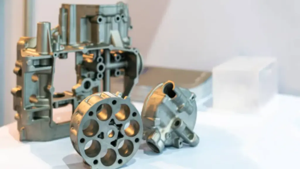
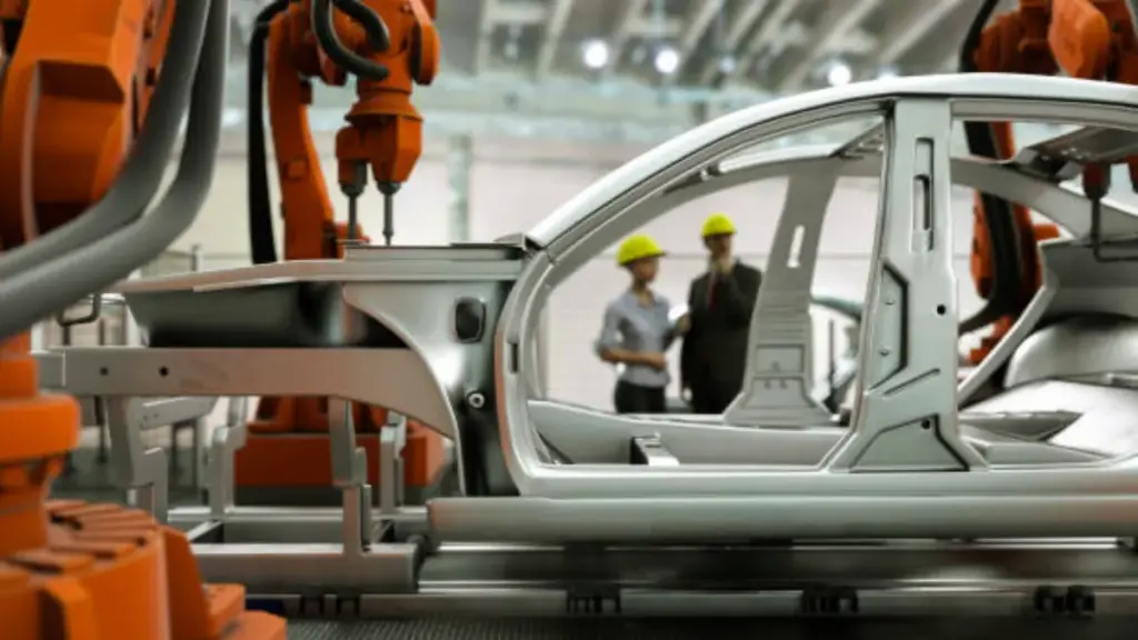
Defeitos desperdiçam recursos intensivos em capital, como horas de máquina em prensas de 9.000 toneladas e altos consumos de energia, reduzindo efetivamente a capacidade geral da planta. Defeitos internos em estruturas de veículos elétricos críticos para a segurança impedem processos de valor agregado, como tratamento térmico T6 e soldagem a laser, limitando a realização potencial de preços em até 30% por quilograma. Além disso, porosidade descontrolada e fechamentos a frio aumentam os riscos a jusante, resultando em reclamações de garantia e ciclos de retrabalho caros necessários para atender aos rígidos padrões de segurança do OEM.
Identificando Porosidade de Gás vs.. Porosidade de encolhimento
| Característica | Porosidade de Gás | Porosidade de encolhimento |
|---|---|---|
| Morfologia | Suave, esférico, vazios arredondados | Duro, irregular, cavidades angulares |
| Textura Interna | Sem recursos, superfície limpa | Dendrítico (semelhante a uma árvore) estrutura visível |
| Localização principal | Regiões superiores, caminhos de fluxo, perto da superfície | Seções grossas, pontos quentes térmicos |
| Assinatura de Raio X | Discreto, manchas escuras isoladas | Irregular, filamentoso, redes interligadas |
Diferenças morfológicas e textura de superfície
A distinção entre defeitos de gás e de contração começa com um exame minucioso da forma e da textura. A porosidade do gás forma-se suavemente, esférico, ou vazios arredondados porque a pressão interna do gás molda a cavidade uniformemente contra o metal em solidificação. Esses vazios normalmente apresentam superfícies internas sem características. Em contraste, a porosidade de contração exibe áspera, irregular, e formas angulares. A superfície interna de um vazio de contração muitas vezes revela uma camada dendrítica “semelhante a uma árvore” estrutura, que a análise metalográfica confirma como um sinal de metal de alimentação insuficiente durante a mudança de fase de líquido para sólido.
A distribuição desses vazios também fornece pistas visuais críticas. Os poros de gás geralmente aparecem como muitos pequenos, buracos isolados espalhados perto da superfície ou presos dentro da parede. O encolhimento geralmente se torna maior, zonas esponjosas interligadas ou tubos que seguem o centro térmico da peça. Uma limpeza, superfície lisa sob ampliação indica origens de gás, enquanto dendritos expostos sinalizam um déficit alimentar.
Padrões de localização e correlação de causa raiz
A localização do defeito dentro da peça fundida está diretamente ligada à sua origem no processo. Os defeitos de gás frequentemente se concentram nas regiões superiores da matriz ou ao longo de caminhos de fluxo turbulentos onde o ar, hidrogênio, ou os vapores do lubrificante ficam presos durante a injeção em alta velocidade. Esses gases aprisionados não podem escapar antes que a camada metálica se solidifique. Por outro lado, defeitos de contração localizados em pontos quentes térmicos, seções grossas, e zonas de última solidificação onde a contração do volume excede a alimentação de metal disponível do biscoito ou do sistema de canal.
A identificação correta determina a solução de engenharia específica necessária. A fundição sob pressão assistida a vácuo visa a porosidade do gás, evacuando o ar antes da injeção, que pode melhorar a resistência à tração em aproximadamente 15% e reduzir significativamente as taxas de sucata. Porosidade de contração, no entanto, exige soluções de gerenciamento térmico, como otimização de portas, ajustes de riser, ou resfriamento direcionado para garantir alimentação contínua. Radiografia (raio X) valida o diagnóstico revelando conectividade: o gás aparece como manchas escuras discretas, enquanto o encolhimento se mostra irregular, redes filamentares.
Como gerenciar fechamentos a frio e erros de funcionamento
| Parâmetro | Faixa ideal | Consequência do defeito |
|---|---|---|
| Velocidade do Portão | 25–45m/s | Baixa velocidade (<20 EM) causa resfriamento; alta velocidade (>50 EM) prende o ar. |
| Temperatura da superfície da matriz | 180–280ºC | Pontos frios congelam frentes de fluxo; calor excessivo causa soldagem. |
| Derreta o superaquecimento | 50–100ºC > líquido | Altas temperaturas (>730°C) induzir porosidade de gás; temperaturas baixas causam desligamentos. |
| Tempo de preenchimento | 20–80ms | O enchimento retardado evita a fusão de fluxos metálicos. |
Mecânica Térmica: Por que as frentes metálicas não se fundem
Os fechamentos a frio se formam quando dois fluxos de metal se encontram dentro da cavidade da matriz, mas não possuem energia térmica para se fundirem completamente.. Esta falha termodinâmica normalmente acontece porque a borda principal do fluxo de metal esfria abaixo de uma margem de temperatura coerente., geralmente 15–25°C acima do ponto líquido da liga. Se o metal cair abaixo deste limite antes que as correntes convirjam, as películas de óxido nas frentes de fluxo não quebram e são soldadas novamente, deixando uma costura visível ou descontinuidade na estrutura de fundição.
A fundição sob pressão requer que o processo de enchimento seja concluído dentro de uma janela rígida de 20 a 80 ms. Se a fase de injeção exceder este limite, a solidificação começa antes que a cavidade atinja a densidade total. Os erros de execução representam eventos extremos de não enchimento, onde a viscosidade aumenta ou a contrapressão impede que o metal alcance seções de parede fina. Os dados indicam que quedas de temperatura de 40 a 55 °C desde a comporta até a última zona a ser preenchida causam esses defeitos, necessitando de mapeamento térmico preciso da ferramenta.
Parâmetros de Processo para Eliminação de Defeitos
A eliminação de defeitos de fluxo começa com o controle rigoroso da temperatura de fusão do alumínio A380, visando 50–100°C acima do liquidus enquanto impõe uma tampa rígida a 730°C para evitar a porosidade do gás. Os engenheiros devem atingir velocidades do metal do portão entre 25 e 45 m/s. Velocidades abaixo 20 m/s permitem resfriamento excessivo da frente de fluxo, enquanto as velocidades excedem 50 m/s introduzem turbulência que interrompe o fluxo. A manutenção desses parâmetros cinemáticos garante que o metal retenha energia suficiente para se fundir ao encontrar.
Os sistemas de fundição sob pressão a vácuo removem a contrapressão na cavidade, oferecendo uma vantagem de processo significativa. Esta tecnologia permite que os operadores reduzam o superaquecimento necessário do fundido em 15–20°C, ajudando a liga a fluir em seções finas sem superaquecimento ou soldagem. Instalações que usam simulação de fluxo Magmasoft podem identificar potenciais pontos frios virtualmente antes de cortar aço. Combinado com IATF 16949 protocolos, essas simulações ajudam os engenheiros a projetar circuitos térmicos que mantêm gradientes globais de temperatura da matriz abaixo de 15°C, garantindo solidificação uniforme.
Alumínio de alta precisão & Fundição sob pressão de zinco
Soluções para Flash, Rebarbas, e marcas de ejetor
Otimizando Parâmetros de Injeção e Geometria do Molde
O controle da formação de flash requer um gerenciamento preciso do perfil de pressão de injeção. Os operadores devem definir o volume de enchimento do primeiro estágio entre 92% e 99.9% da capacidade da cavidade para completar o tiro sem força excessiva. A pressão de empacotamento subsequente deve permanecer abaixo 500 psi para evitar que o metal fundido force linhas de separação abertas ou escape pelas aberturas. Quando o flash persiste perto de áreas de ventilação, engenheiros modificam o molde reduzindo a profundidade e largura da ventilação, equilibrando a evacuação de gás com a contenção.
As marcas do ejetor normalmente resultam de alto estresse mecânico durante a remoção da peça. Para mitigar isso, os projetistas de moldes costumam adicionar 0.05 mm para 0.2 mm de material nos locais dos pinos ejetores, criando um terreno ligeiramente elevado que difunde o estresse e simplifica o acabamento. Se ocorrer deformação côncava em áreas salientes, aumentar o diâmetro dos pinos ejetores ou adicionar mais pinos distribui a força de ejeção de maneira mais uniforme, evitando distorção da superfície.
Padrões automatizados de rebarbação e aceitação de qualidade
Os padrões da indústria para qualidade de superfície definem limites claros para defeitos residuais. Peças fundidas sob pressão de primeira classe não exigem rebarbas detectáveis, enquanto superfícies de segunda classe permitem alturas de rebarbas abaixo 0.2 milímetros. Para atender consistentemente a essas métricas, fabricantes implantam sistemas robóticos de rebarbação com múltiplas ferramentas que combinam corte, moagem, e lixamento de cinta. Essas soluções automatizadas removem mais 90% de rebarbas de linha de partição e cascos convexos, garantindo conformidade dimensional sem intervenção manual.
Para pequenas imperfeições superficiais, como marcas leves de pinos ejetores, técnicas de pós-processamento, como polimento e jato de areia, combinam efetivamente a textura antes da anodização ou pintura. Estas etapas de remediação garantem que as necessidades estruturais, como pontos ejetores, não comprometa o valor estético do componente final.
O papel dos testes não destrutivos (END)
Testes não destrutivos servem como principal porta de qualidade para componentes automotivos, empregando cinco métodos principais: ultrassônico, raio X, partícula magnética, líquido penetrante, e corrente parasita. Essas técnicas validam a solidez interna e a integridade da superfície sem comprometer a peça, aderindo a padrões rigorosos como ASTM E155 para garantir confiabilidade em aplicações estruturais de alto estresse.
Métodos primários de END para detecção de defeitos
Radiográfico (raio X) a inspeção funciona como o método fundamental para revelar variações de porosidade e densidade, particularmente em peças fundidas seccionadas mais pesadas, onde a consistência interna determina a viabilidade estrutural. Capturando uma imagem volumétrica do componente, os técnicos podem localizar bolsas de gás ou cavidades de contração que permanecem invisíveis para verificações visuais externas. Para complementar a radiografia, o teste ultrassônico transmite ondas sonoras de alta frequência através do material para identificar vazios internos profundos e bolsas de ar, fornecendo dados de profundidade que as imagens planares de raios X podem não resolver completamente.
Para integridade superficial e próxima da superfície, testes de partículas magnéticas e líquidos penetrantes são implantados especificamente para detectar trincas superficiais e descontinuidades externas. Esses métodos são essenciais para identificar locais de início de fadiga em superfícies usinadas. Adicionalmente, O teste de correntes parasitas aplica indução eletromagnética para medir propriedades e condutividade do material, oferecendo uma maneira não intrusiva de verificar se a composição da liga e os estados do tratamento térmico atendem às especificações sem alterar a peça.
Padrões de teste e integração de alto vácuo
A garantia de qualidade automotiva depende da adesão estrita aos benchmarks do setor, especificamente ASTM E155 para radiografias de referência padrão e ASTM B557 para testes de tensão de ligas de alumínio. Estas normas definem os limites aceitáveis para a severidade da descontinuidade, garantindo que cada lote atenda às linhas de base mecânicas exigidas para sistemas críticos de segurança. Protocolos de validação frequentemente combinam esses padrões para verificar propriedades mecânicas em ligas de alumínio com baixo teor de ferro (≤0,25% de teor de ferro), que são propensos a tipos de defeitos específicos se o controle do processo sofrer desvios.
Na fundição sob pressão de alto vácuo, O END integra-se diretamente com a validação do tratamento térmico. Como as peças assistidas por vácuo passam por tratamentos térmicos T5 ou T6 – envolvendo têmpera em água a temperaturas entre 150°C e 250°C – os testes devem confirmar que a microestrutura evoluiu corretamente. Engenheiros avaliam parâmetros como espaçamento de braço dendrítico secundário (SDAS) para caracterizar a finura da microestrutura, garantindo que o processo de fundição avançado eliminou com sucesso a porosidade e alcançou a resistência pretendida do material.
Aplicando o método de resolução de problemas 8D
O 8D (Oito Disciplinas) método é um padrão estruturado de resolução de problemas originalmente desenvolvido pela Ford em 1987. Ele orienta equipes multifuncionais em oito etapas – desde a formação de uma equipe e a descrição do problema usando a análise IS/IS-NOT até a implementação de ações corretivas permanentes e prevenção de recorrências – garantindo uma fabricação com zero defeitos em conformidade com a IATF 16949.
A Estrutura 8D: Origens e padrões automotivos
O 8Metodologia D originou-se na Ford Motor Company em 1987 e tornou-se o padrão global para lidar com falhas recorrentes de produtos no setor automotivo. Estruturas de qualidade modernas, incluindo a Associação Alemã da Indústria Automotiva (VDA), agora exigem ferramentas analíticas específicas dentro da estrutura 8D. As equipes devem utilizar a análise IS/IS-NOT – derivada da metodologia Kepner-Tregoe – durante a fase de definição do problema para garantir um escopo rigoroso antes de tentar uma solução.
Bian Metal integra esta metodologia diretamente na IATF 16949 protocolos para gerenciar a qualidade do elenco de alto risco. O processo começa com Disciplina 1 (D1), que requer o estabelecimento de uma equipe multifuncional composta por engenheiros de processo, gerentes de qualidade, e operadores de máquinas. Essa abordagem colaborativa garante que defeitos complexos, como porosidade intermitente ou desvio dimensional, são analisados a partir de múltiplas perspectivas técnicas, em vez de depender do julgamento de um único operador.
Execução passo a passo: Da Contenção à Correção Permanente
O núcleo do processo 8D baseia-se na distinção entre o manejo imediato dos sintomas e a eliminação da causa raiz em longo prazo.. Durante D2 (Descrição do problema) e D4 (Análise de causa raiz), as equipes empregam diagramas de Ishikawa e portas lógicas para separar os sintomas dos defeitos de suas origens. Por exemplo, os técnicos devem diferenciar entre a porosidade do gás causada pelo ar aprisionado e a porosidade de contração causada por gradientes térmicos, pois a identificação incorreta leva a contramedidas ineficazes.
As etapas de ação são estritamente divididas em contenção e prevenção. D3 foca em ações imediatas de contenção, como classificar estoque ou instalar filtros temporários, para proteger o cliente de receber peças defeituosas. Em contraste, D7 visa mudanças sistêmicas, como atualizar projetos de moldes ou revisar layouts de canais de resfriamento, para prevenir a recorrência. Entre esses estágios está D6 (Validação), um crítico “tente uma correção e monitore” fase. Aqui, os engenheiros implementam a ação corretiva em pequena escala e coletam dados para confirmar que o defeito foi eliminado antes de autorizar alterações de produção em grande escala.
Como manter a consistência na produção em massa
A consistência na produção em massa depende do bloqueio de variáveis antes do primeiro disparo. Isto envolve aderir à NADCA e ISO 8062 padrões de tolerância durante a fase de projeto e aplicação rigorosa dos parâmetros do processo - especificamente pressão de injeção (70–140 MPa) e temperatura de fusão – usando sistemas de monitoramento automatizados para garantir que cada ciclo reproduza as configurações mestre validadas.
Alinhando o Design com os Padrões NADCA e Protocolos DFM
Alcançar qualidade uniforme em tiragens de alto volume começa com a definição de especificações rígidas. Os fabricantes usam os Padrões de Especificação de Produto NADCA para distinguir entre “Padrão” e “Precisão” tolerâncias, com diretrizes de precisão oferecendo até 65% controle dimensional mais rígido do que os valores legados da Série E. ISO 8062 serve como dimensionamento geométrico e tolerância (GD&T) linha de base, limitando o desvio permitido para recursos críticos. A consistência química é igualmente vital; aderindo à ASTM B85 (Alumínio) ou ASTM B86 (Zinco) os padrões garantem que o comportamento de fusão da liga e as taxas de encolhimento permaneçam estáveis de lote para lote, evitando variações inesperadas no elenco final.
Design para Fabricação (DFM) protocolos traduzem esses padrões em geometria física que resiste à distorção. Os engenheiros aplicam regras para espessura de parede uniforme e ângulos de inclinação otimizados para garantir que a peça esfrie uniformemente e seja ejetada de maneira limpa, sem empenamento induzido por tensão. Ao abordar a potencial distorção térmica durante a fase de projeto, os fabricantes reduzem o risco de desvio dimensional que geralmente ocorre quando geometrias complexas interagem com altos gradientes térmicos.
Controlando os parâmetros de injeção e a repetibilidade do ciclo
Assim que a produção começar, consistência depende do controle ativo do processo. Fundição sob pressão (HPDC) sistemas mantêm as pressões de injeção entre 10,000 e 20,000 psi (70–140 MPa) para garantir preenchimento e densidade completos da cavidade. Regular a temperatura de fusão – aproximadamente 700°C para o alumínio – é fundamental; mesmo pequenas alterações de viscosidade causadas por flutuações de temperatura podem causar porosidade ou fechamento a frio. Sistemas de monitoramento automatizados rastreiam essas variáveis em tempo real, acionando alarmes se os parâmetros saírem da janela do processo validado.
Tecnologias avançadas de simulação e inspeção garantem ainda mais a repetibilidade. Antes do início da ferramentaria, engenheiros usam simulação MAGMASOFT para prever padrões de fluxo e definir projetos de canais ideais, eliminando a variabilidade de tentativa e erro. Durante a produção, Máquinas de medição por coordenadas (CMMs) e digitalização 3D realizam auditorias dimensionais frequentes. Essas ferramentas detectam sinais precoces de desgaste da ferramenta ou desvio térmico, permitindo que os operadores realizem manutenção ou ajustes antes que as peças saiam da tolerância.
Excelência automotiva completa: Do molde à entrega global
Seu parceiro de fabricação verticalmente integrado, Bian Diecast, simplifica sua cadeia de suprimentos, oferecendo uma solução perfeita, solução completa. Gerenciamos todo o ciclo de vida da produção internamente - desde o design de molde de precisão e vácuo Fundição sob pressão para usinagem CNC e tratamento de superfície. Eliminando a necessidade de vários fornecedores, reduzimos seus custos de coordenação e encurtamos os prazos de entrega em até 30%.
- Confiabilidade de nível automotivo: Operando sob IATF 16949 padrões, utilizamos simulação Magmasoft® e inspeção por raios X em tempo real para garantir consistência sem defeitos para componentes de EV e trem de força críticos para a segurança.
- Gerenciamento sem complicações: Nosso “Parada única” modelo significa que assumimos total responsabilidade pela qualidade e montagem em todas as fases, fornecendo a você um ponto único de responsabilidade e total tranquilidade.
- Resiliência da cadeia de suprimentos global: Com bases de produção duplas em China e México, oferecemos aos clientes norte-americanos fabricação perto da costa, mitigação de risco tarifário, e rápido, entrega localizada.
Considerações Finais
O controle de defeitos na fundição automotiva exige uma estratégia de engenharia proativa, em vez de um processo de classificação reativo. O sucesso depende do domínio das variáveis críticas – temperatura de fusão, velocidade de injeção, e geometria do molde – antes que o primeiro tiro entre na matriz. Mudando o foco da detecção de erros para a prevenção deles por meio de ferramentas como simulação Magmasoft e monitoramento rigoroso de processos, os fabricantes podem eliminar o desperdício financeiro da sucata e, ao mesmo tempo, atender aos padrões de segurança exigidos para veículos modernos.
A confiabilidade define o valor de qualquer parceiro da cadeia de fornecimento automotivo. Aderindo a protocolos rígidos como IATF 16949 e a utilização de métodos avançados de END garante que os componentes estruturais funcionem corretamente sob pressão. Quando os fundidores integram essas metodologias de zero defeito diretamente em seu fluxo de trabalho, eles protegem os resultados financeiros e a reputação da marca, fornecendo peças que atendem às rigorosas demandas da estrada.
Perguntas frequentes
O que causa a porosidade do gás na fundição sob pressão?
A porosidade do gás é causada principalmente pelo ar preso na cavidade da matriz ou pelo metal fundido durante as fases de injeção. À medida que a fundição se solidifica, este gás preso se expande para compensar o encolhimento. O problema geralmente é resolvido otimizando a capacidade de ventilação, ajustando a velocidade do tiro, e garantir que a lubrificação não introduz excesso de gás.
Como você conserta fechamentos a frio em fundição de alumínio?
Os fechamentos a frio ocorrem quando dois fluxos de metal se encontram, mas não conseguem se fundir completamente. Corrigir isso normalmente envolve aumentar a temperatura de fusão (acima de 660°C) e morrer temperatura (acima de 180°C), aumentando a velocidade do tiro e a pressão específica, ou encurtando caminhos de fluxo através de reprojetos de canais para manter o metal quente durante o enchimento.
Qual é a diferença entre bolha e porosidade?
Porosidade refere-se a vazios internos (causada por gás ou encolhimento) em qualquer lugar dentro do volume de fundição. Uma bolha é um defeito superficial específico que ocorre quando a porosidade do gás próximo à superfície se expande – geralmente durante o tratamento térmico – e empurra a pele da peça fundida para fora., criando uma protuberância visível.
Como funciona a IATF 16949 defeitos de alça padrão?
IATF 16949 muda o foco da detecção para a prevenção. Exige que os fabricantes usem o modo de falha de processo e a análise de efeitos (PFMEA) identificar riscos antecipadamente e implementar soluções à prova de erros (Poka Yoke) dispositivos. Se ocorrerem defeitos, um processo estruturado de resolução de problemas é obrigatório para identificar causas raiz verificáveis, em vez de apenas resolver as partes ruins.
Quais são os critérios típicos de aceitação para defeitos de acabamento superficial?
Os critérios dependem da função da superfície. Para vedação crítica ou zonas de alto estresse, os poros são frequentemente limitados a ≤0,3 mm de profundidade e ≤0,5 mm de diâmetro. Para áreas visuais gerais, padrões como ASTM A802 são usados, permitindo menor, descontinuidades dispersas, desde que não se agrupem ou penetrem na espessura da parede.
Como evitar marcas de fluxo em peças visuais?
A prevenção de marcas de fluxo requer controle rigoroso de temperatura e padrões de enchimento suaves. As melhores práticas incluem manter o fundido do alumínio entre 660–700°C e a temperatura da matriz entre 180–220°C. Adicionalmente, a comporta deve ser projetada para evitar que frentes metálicas turbulentas ou frias se assentem em superfícies cosméticas Classe A.