Decisões erradas de DFM no projeto de caixas de luz fundidas geralmente levam a problemas dispendiosos, como porosidade, empenamento, falhas de vedação, e modificações de ferramentas. Muitos desses problemas se originam durante a fase de projeto e tornam-se caros para serem corrigidos quando a produção de ferramentas começa.
Este guia cobre as principais regras do DFM para caixas de luz fundidas, incluindo ângulos de inclinação, espessura da parede, subsídios de usinagem, projeto de superfície de vedação, e controle de risco de ferramentas. Ao aplicar estas diretrizes antecipadamente, os fabricantes podem melhorar a capacidade de fabricação, reduzir riscos de produção, reduzir custos gerais, e alcançar uma qualidade mais consistente desde o desenvolvimento de protótipos até a produção em massa.
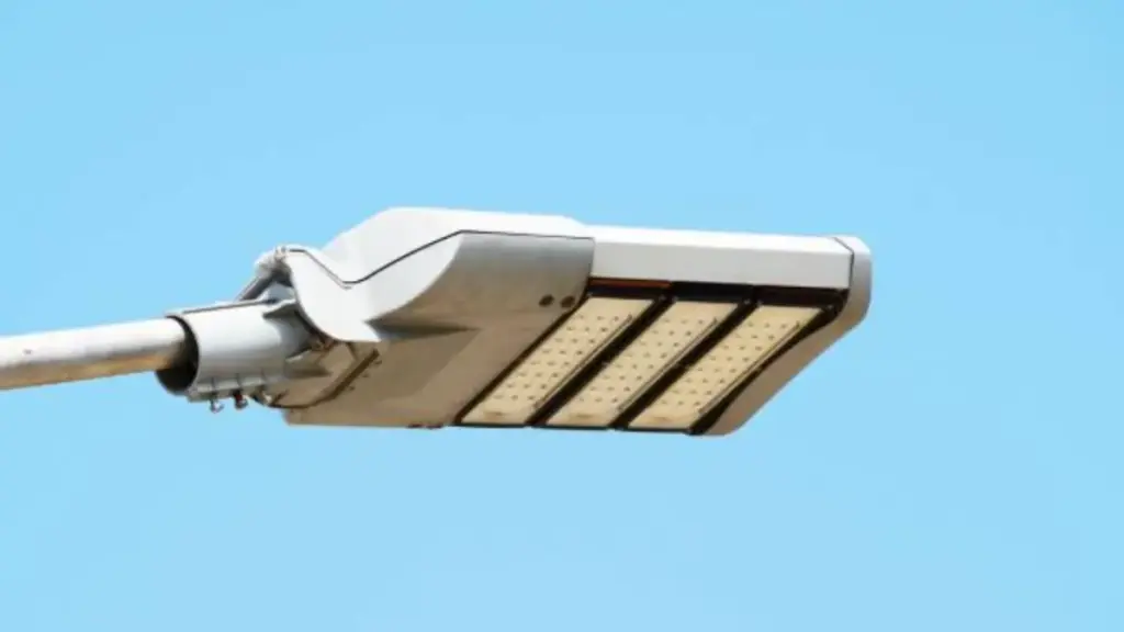
Noções básicas de DFM para carcaça leve fundida
O projeto bem-sucedido de carcaças de luz fundidas começa com DFM. A avaliação precoce dos principais fatores de design ajuda a melhorar a qualidade, reduzir o risco, e apoiar a produção em massa eficiente.
Por que o DFM é fundamental para caixas leves fundidas
Carcaças leves combinam suporte estrutural, dissipação de calor, e proteção de vedação em uma parte. Isso os torna sensíveis a pequenas mudanças na espessura, geometria, e qualidade da superfície.
Sem DFM adequado, problemas geralmente aparecem durante o teste ou produção em massa, quando as modificações se tornam caras e lentas.
Problemas comuns incluem:
- Porosidade e defeitos: Paredes irregulares ou desequilíbrio térmico reduzem a resistência e o desempenho da vedação.
- Problemas de ejeção: Calado insuficiente ou geometria vertical complexa aumentam o emperramento e o desgaste da ferramenta.
- Vazamento de água: Um projeto de vedação deficiente ou deformação reduz o desempenho da junta.
- Alto custo de usinagem: A falta de licenças aumenta a carga de trabalho do CNC.
- Atrasos nas ferramentas: Defeitos encontrados após testes exigem modificação da matriz.
Estes problemas estão muitas vezes ligados. Por exemplo, a porosidade perto das zonas de vedação pode reduzir diretamente o desempenho do IP, enquanto a usinagem extra pode expor defeitos internos.
Você pode aprender mais sobre Dicas de design de caixa de LED em alumínio fundido em nosso artigo dedicado.
Requisitos funcionais que moldam o projeto de habitação
DFM requer força de equilíbrio, comportamento térmico, impermeabilização, precisão dimensional, e aparência no nível do sistema. Esses fatores muitas vezes competem, portanto, as compensações de design são inevitáveis.
| Exigência | Foco no design |
|---|---|
| Resistência Estrutural | Estrutura apoiada em nervuras com espessura de parede controlada |
| Desempenho térmico | Dissipação de calor eficiente com fluxo de fundição estável |
| Impermeabilização | Interface de vedação contínua com planicidade controlada |
| Precisão dimensional | Pontos de referência estáveis com tolerâncias de usinagem definidas |
| Qualidade Estética | Linha de partição otimizada e controle de acabamento superficial |
Principais áreas revisadas durante uma análise DFM
Uma revisão estruturada do DFM avalia o comportamento do elenco, viabilidade de usinagem, e estabilidade de montagem durante todo o ciclo de produção.
| Área DFM | Propósito |
|---|---|
| Ângulos de inclinação | Garanta uma ejeção suave e reduza o desgaste da matriz durante ciclos repetidos |
| Posição da linha de partição | Evite vedações e superfícies visíveis para reduzir rebarbas e trabalhos de acabamento |
| Espessura da Parede & Costelas | Mantenha o resfriamento equilibrado e reduza defeitos de contração |
| Recursos de usinagem | Defina áreas de acabamento CNC para controle de tolerância rígido |
| Vedação de interfaces | Garanta um desempenho estável à prova d'água com classificação IP |
| Comportamento do fluxo do molde | Identifique riscos de enchimento e armadilhas de ar antes da produção de ferramentas |
Você pode estar interessado em: O que é molde de fundição sob pressão?
Materiais de fundição sob pressão: O que você precisa saber
Regras de ângulo de inclinação e linha de partição
O ângulo de inclinação e o design da linha de partição afetam diretamente a estabilidade de ejeção, qualidade da superfície, e vida útil da ferramenta. Esses dois parâmetros influenciam fortemente a consistência de fabricação a longo prazo na fundição sob pressão.
Ângulos de inclinação recomendados para diferentes características de alojamento
Os requisitos de ângulo de inclinação variam dependendo da geometria do recurso. Em caixas de luz fundidas, aletas do dissipador de calor, montagem de chefes, e estruturas de vedação geralmente exigem valores de tiragem diferentes para garantir uma ejeção suave e uma qualidade consistente da peça.
| Recurso | Ângulo de inclinação |
|---|---|
| Paredes Externas | 1°–2° |
| Paredes Internas | 2°–3° |
| Bolsos profundos | 2°–5° |
| Superfícies Texturizadas | 3°+ |
| Aletas do dissipador de calor | 1°–3° |
As cavidades internas exigem maior tiragem porque se fixam mais firmemente ao núcleo durante o resfriamento. As faces externas se soltam mais facilmente, mas ainda precisam de conicidade controlada para evitar danos à superfície.
A seleção adequada da tiragem melhora a estabilidade de ejeção e reduz o desgaste da matriz, mesmo em geometrias complexas ou compactas.
Melhores práticas para posicionamento de linhas de partição
A linha de partição define a separação do molde e afeta diretamente o controle de flash, qualidade de vedação, e custo de acabamento. Uma vez corrigido, mudanças são difíceis e caras.
Regras principais:
- Integridade de vedação: Evite zonas de vedação e vedação IP
- Controle visual: Mantenha longe de superfícies visíveis
- Alinhamento geométrico: Siga bordas naturais
- Simplicidade da ferramenta: Prefira linhas divididas retas
- Estabilidade de fluxo: Apoie o enchimento equilibrado
Para caixas de iluminação, as superfícies de vedação nunca devem cruzar a linha de partição, já que mesmo um flash menor pode reduzir o desempenho do IP.
Problemas comuns de qualidade decorrentes de design deficiente
Decisões de rascunho e linha de partição afetam fortemente a estabilidade da produção, especialmente na produção em massa de componentes complexos de alumínio, como caixas de luz fundidas.
- Estresse de ejeção: A baixa tiragem aumenta o atrito e os danos à superfície
- Desgaste da ferramenta: Maior resistência reduz a vida útil da matriz
- Formação de flash: O desalinhamento requer corte extra
- Risco de vedação: Flash perto de zonas de vedação pode causar vazamento
- Retrabalho de montagem: O acabamento extra aumenta o custo e o tempo de ciclo
Esses problemas geralmente aparecem juntos. Por exemplo, alta força de ejeção aumenta os danos à superfície, enquanto o flash perto de áreas de vedação reduz diretamente a confiabilidade do IP.
Seu parceiro completo para fundição sob pressão de precisão
Espessura da parede e design das nervuras
A estabilidade estrutural e o comportamento térmico em caixas fundidas sob pressão dependem de como as paredes e as nervuras estão dispostas. Um design deficiente geralmente leva a defeitos como porosidade, empenamento, e comportamento de resfriamento instável.
Faixas de espessura de parede recomendadas para caixas leves
A espessura da parede influencia fortemente o comportamento do enchimento, velocidade de resfriamento, e estabilidade dimensional final. Na maioria das caixas de iluminação de alumínio, 2.0–4,0 mm fornece um equilíbrio prático entre resistência e capacidade de fabricação. Mais importante que a espessura é a consistência em toda a estrutura.
Paredes uniformes ajudam a manter condições de fundição estáveis:
- Estabilidade de fluxo metálico: Reduz a turbulência e o enchimento incompleto
- Equilíbrio de resfriamento: Evita solidificação irregular
- Controle Dimensional: Reduz o risco de empenamento após a ejeção
- Redução de defeitos: Evita o encolhimento em zonas espessas
Quando mudanças são necessárias, transições suaves funcionam melhor do que passos bruscos porque reduzem a concentração de estresse e a interrupção do fluxo.
Regras de design de costelas para redução de força e peso
As nervuras melhoram a rigidez sem aumentar significativamente o uso de material. Comparado com seções sólidas espessas, eles fornecem uma estrutura térmica e mecânica mais estável.
| Parâmetro de projeto | Recomendação |
|---|---|
| Espessura das Costelas | 50–70% da espessura da parede |
| Costela | ≥ 1° |
| Raio Base | Filé generoso para reduzir o estresse |
| Layout de costela | Costelas distribuídas preferidas em vez de costela única grossa |
Um layout de nervuras distribuídas melhora a distribuição de carga e reduz o desequilíbrio térmico local durante o resfriamento.
Prevenindo a Porosidade, Marcas de pia, e empenamento
Muitos defeitos provêm de projetos de seções irregulares, e não apenas da instabilidade do processo. Um problema típico é uma saliência espessa conectada a paredes finas, o que cria resfriamento desigual e encolhimento interno.
Para reduzir esses riscos, os designers deveriam:
- Seções grossas ocas: Reduzir a massa térmica
- Use suporte de costela: Substitua material a granel por estrutura
- Mantenha a consistência da parede: Evite mudanças repentinas de espessura
- Fluxo de calor de equilíbrio: Melhore a uniformidade geral do resfriamento
Em caixas de LED, costelas também ajudam a conduzir o calor para longe da fonte de luz, melhorando o desempenho térmico geral.
Permissão de usinagem e planejamento de dados
O desempenho da usinagem depende diretamente de quão bem as tolerâncias e as referências de referência são definidas durante o projeto.
Determinando tolerâncias de usinagem adequadas
Embora a fundição sob pressão forneça boa precisão de formato quase final, A usinagem CNC ainda é necessária para interfaces funcionais. Essas áreas devem ser planejadas cuidadosamente para evitar cortes em zonas defeituosas ou deixar excesso de estoque que aumente os custos.
As tolerâncias típicas de usinagem dependem da sensibilidade do recurso:
| Tipo de recurso | Permissão de usinagem |
|---|---|
| Superfícies de montagem padrão | 0.25–0,5mm |
| Superfícies de vedação de precisão | 0.5–1,0 mm |
| Furos roscados | Com base no tamanho da ferramenta + margem de limpeza |
O excesso de margem de usinagem aumenta o tempo de corte e pode expor a porosidade oculta. Muito pouco subsídio, no entanto, torna impossível atingir as tolerâncias exigidas. O ponto de equilíbrio é sempre orientado pela função, não orientado por processos.
Estabelecendo referências de dados estáveis
Um sistema de referência estável garante usinagem e inspeção consistentes em todas as etapas da produção. A má seleção de dados leva a erros cumulativos e incompatibilidade de montagem.
Princípios-chave:
- Dado Primário: Superfície de suporte principal para estabilidade
- Dado Secundário: Controla a precisão da orientação
- Dado Terciário: Garante precisão posicional na usinagem CNC
Grandes superfícies fundidas contínuas devem sempre ser priorizadas como referências de referência.
- Princípio de estabilidade de dados: Superfícies maiores melhoram a repetibilidade da medição
- Regra da linha de partição: Evite usar linhas de partição devido a incompatibilidade e variação de flash
Projetando peças fundidas para usinagem CNC eficiente
O DFM deve alinhar a geometria da peça fundida com a acessibilidade do CNC e a eficiência da fixação. A má coordenação geralmente resulta em longos tempos de configuração e usinagem instável.
Principais regras de otimização:
- Otimização de acessibilidade: Certifique-se de que os caminhos da ferramenta estejam desobstruídos
- Princípio de redução de configuração: Minimize as alterações de fixação para melhorar a eficiência
- Eficiência do caminho da ferramenta: Simplifique a geometria para reduzir o tempo de troca de ferramentas
A coordenação precoce entre fundição e projeto de usinagem reduz significativamente o retrabalho e melhora a estabilidade da produção.
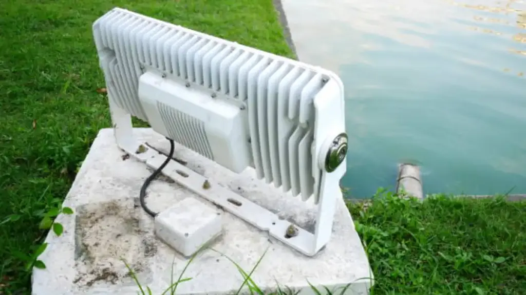
Superfície de vedação e projeto de entrada de cabos
O desempenho à prova d'água em caixas de luz fundidas depende de quão bem as áreas de vedação e as estruturas de entrada de cabos resistem à deformação, vazamento, e estresse ambiental.
Projetando superfícies de vedação confiáveis para caixas com classificação IP
Invólucros externos operando sob IP65–IP67 exigem zonas de vedação estáveis. Mesmo pequenos defeitos superficiais podem quebrar a compressão da junta e causar caminhos de vazamento.
Para garantir um desempenho de vedação confiável, os principais controles de design incluem:
- Controle de planicidade: Garante compressão uniforme da junta
- Continuidade de Superfície: Mantém um contato de vedação estável e ininterrupto
- Integridade Material: Reduz o risco de vazamento causado pela porosidade
- Controle de usinagem: Garante a precisão da vedação final após a fundição
Por causa desses requisitos, as superfícies de vedação geralmente são acabadas por usinagem secundária em vez de depender de superfícies fundidas brutas. Defeitos como marcas de ejetor, flash da linha de separação, e zonas de encolhimento devem ser estritamente evitadas nesta área.
Para uma explicação mais profunda Acabamento de superfície para peças fundidas sob pressão, nós cobrimos isso em um artigo separado.
Melhores práticas para recursos de entrada de cabos
A entrada de cabos é uma das áreas de maior risco em caixas externas porque combina abertura, vedação, e proteção de isolamento em um espaço limitado.
Um design estável deve garantir:
- Compatibilidade padrão: Funciona com prensa-cabos comuns
- Resistência Estrutural: Evita rachaduras durante a instalação
- Simplicidade de montagem: Reduz erros de instalação
- Proteção de Cabo: Evita danos por arestas vivas no isolamento
A colocação também é importante. A entrada do cabo descendente ou vertical reduz o acúmulo de água e melhora a estabilidade da vedação a longo prazo.
Equilibrando os requisitos impermeáveis e térmicos
Para caixas de luz fundidas usadas em iluminação LED externa, o gerenciamento térmico e a confiabilidade à prova d’água muitas vezes competem entre si. O acúmulo de calor pode degradar gradualmente os materiais da junta, enquanto as restrições de vedação podem limitar os caminhos de dissipação de calor. Um projeto estável deve tratar ambos como um sistema conectado. Isolamento térmico, rigidez estrutural, e a distribuição controlada de calor trabalham juntas para manter o desempenho IP de longo prazo durante todo o ciclo de vida do produto.
Recursos que aumentam o risco de ferramentas
Certas características de projeto podem aumentar significativamente o custo das ferramentas de fundição sob pressão e reduzir a estabilidade da produção.
Recursos geométricos que complicam a construção de ferramentas
Certas estruturas geométricas aumentam diretamente a complexidade do molde e exigem mecanismos de ferramentas adicionais. Esses recursos afetam o custo e a frequência de manutenção.
Geometrias comuns de alto risco incluem:
- Cortes inferiores: Exigir corrediças ou elevadores para permitir a liberação da peça
- Cavidades profundas e estreitas: Aumenta a dificuldade de enchimento e o risco de aprisionamento de ar
- Barbatanas estendidas finas: Reduza a estabilidade do fluxo durante a injeção
- Cantos internos afiados: Aumenta a concentração de tensão e o desgaste da matriz
Estas estruturas muitas vezes forçam componentes móveis adicionais no molde, o que aumenta o tempo de ciclo e o custo de manutenção a longo prazo.
Opções de projeto que aumentam as taxas de sucata e o desgaste de ferramentas
Além da geometria, certas decisões de projeto afetam diretamente o rendimento da produção e a vida útil da ferramenta. Esses problemas geralmente aparecem durante a produção experimental, quando o custo de correção já é alto.
| Problema de projeto | Impacto na produção |
|---|---|
| Espessura de parede irregular | Porosidade e empenamento dimensional |
| Rascunho insuficiente | Resistência à ejeção e desgaste da matriz |
| Projeto de ventilação ruim | Porosidade de gás e defeitos superficiais |
| Excesso de requisitos cosméticos | Maior custo de polimento e manutenção de ferramentas |
Esses problemas podem não afetar as amostras iniciais, mas reduzem significativamente a consistência durante longos ciclos de produção.
Usando DFM e análise de fluxo de molde para reduzir o risco de ferramentas
O desenvolvimento moderno de fundição sob pressão depende cada vez mais de ferramentas de simulação combinadas com revisão DFM. Esta abordagem melhora a tomada de decisões antes do investimento em ferramentas.
Os principais resultados da análise incluem:
- Previsão de preenchimento: Identifica desequilíbrio de fluxo e risco de curto alcance
- Detecção de armadilha aérea: Localiza zonas potenciais de porosidade de gás
- Análise de resfriamento: Avalia o risco de encolhimento e deformação
- Otimização de portão: Melhora a distribuição do fluxo e o equilíbrio da pressão
- Planejamento de redução de ferramentas: Minimiza slides ou inserções desnecessárias
Para caixas de iluminação complexas, essa abordagem combinada ajuda a reduzir iterações de projeto e melhora o sucesso das ferramentas na primeira tentativa.
A identificação precoce de riscos permite que os fabricantes evitem alterações dispendiosas nos moldes e encurtem o caminho para uma produção em massa estável.
Perguntas frequentes
O que é DFM na fundição sob pressão?
Design para Manufaturabilidade (DFM) na fundição sob pressão é o processo de projetar peças para serem produzidas de forma confiável, a um custo baixo, e com qualidade consistente. Para caixas leves, DFM se concentra no alinhamento da geometria, escolha de liga, e layout da ferramenta com os requisitos para fundição, ejeção, usinagem, e acabamento para evitar defeitos antes da criação do ferramental.
Qual ângulo de inclinação é necessário para peças fundidas sob pressão?
Para caixas de luz fundidas em alumínio, um calado de linha de base de 1°–2° por lado é típico para a maioria das paredes. Paredes mais profundas (>50 milímetros) ou costelas finas podem exigir 1,5°–3°. Superfícies de montagem críticas às vezes podem usar apenas 0,5°–1°. Recursos com contato deslizante metal-metal, como desligamentos, precisa de 3° ou mais para evitar desgaste.
Como as linhas de partição afetam o projeto de fundição?
A linha de separação, onde as duas metades da matriz se encontram, afeta o custo do ferramental, aparência cosmética (deixando uma costura visível), precisão dimensional, e formação de flash. Para melhores resultados, as linhas de separação devem ser tão planas quanto possível, localizado em superfícies não críticas, e não deve cruzar com faces de vedação críticas, a menos que essas faces sejam totalmente usinadas após a fundição.
Quais recursos aumentam o custo das ferramentas de fundição sob pressão?
Os custos de ferramentas aumentam significativamente com recursos como cortes inferiores (que exigem slides), linhas de partição complexas ou não planas, tolerâncias apertadas, e altos requisitos de superfície cosmética. Outros fatores de custo importantes incluem peças de grande porte, a necessidade de múltiplas cavidades, e sistemas de resfriamento complexos para gerenciar espessuras de parede não uniformes.
Como você projeta superfícies de vedação em caixas fundidas sob pressão?
Para obter uma vedação confiável (por exemplo, IP67), as superfícies de vedação são normalmente usinadas em CNC para garantir planicidade e um acabamento superficial específico. O projeto deve incluir rigidez suficiente do flange e espaçamento uniforme dos fixadores. Também é fundamental usar controles de processo, como fundição a vácuo, para minimizar a porosidade sob a superfície usinada., que de outra forma poderia criar caminhos de vazamento.
Quando a revisão do DFM deve acontecer antes da ferramentaria?
Uma revisão do DFM deve ser totalmente concluída e assinada antes de qualquer ferramenta de produção ser encomendada ou o aço ser cortado. Esta revisão deverá acontecer após a validação do projeto 3D inicial com protótipos. Fazer alterações após o início da ferramentaria leva a aumentos de custos significativos, atrasos no projeto, e possíveis problemas de qualidade.
Considerações Finais
Um sucesso carcaça de luz fundida depende de quão bem os principais princípios do DFM e as restrições de fabricação são aplicados desde o início. Ângulos de rascunho, espessura da parede, estruturas de costela, subsídios de usinagem, e superfícies de vedação afetam diretamente a estabilidade da produção, controle de custos, e confiabilidade a longo prazo.
Para fabricantes que otimizam produtos existentes ou desenvolvem novos designs, uma abordagem inicial de DFM ajuda a reduzir o risco de ferramentas e a acelerar o tempo de lançamento no mercado. Bian Diecast fornece revisão de DFM de fundição sob pressão e suporte de fabricação para ajudar a garantir uma transição mais suave do projeto para a produção em massa.