Many engineering teams select a casting process based on past projects, overlooking how this specific method can drastically cut cycle times and per-unit costs for certain alloys. This seemingly small decision at the start can lock a project into inefficient workflows, creating budget overruns that surface much too late in the production schedule.
This guide provides a clear technical framework for deciding between casting processes. We will analyze the mechanics of the gooseneck injection system, run a direct comparison between hot and cold chamber casting, and specify the ideal zinc and magnesium alloys for the job. You will also get actionable design guidelines for part manufacturing and a practical overview for identifying and preventing common casting defects before they impact your final component quality.
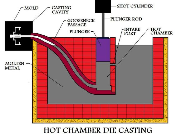
The Hot Chamber Die Casting Process: How the Gooseneck System Works
The gooseneck’s submerged design enables automated, continuous metal feeding, which is the mechanical basis for the rapid cycle times in hot chamber die casting.
Core Components and Material Construction
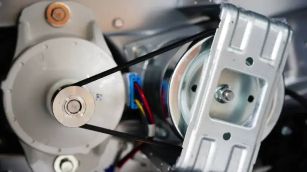
The gooseneck system is the central component of a hot chamber machine, functioning as a submerged feed conduit that sits directly in the molten metal bath. This component houses both the hot chamber and the hydraulic injection plunger, creating a direct path from the furnace to the die. Due to its constant immersion and exposure to intense thermal stress, the gooseneck is manufactured from high-quality cast or forged steel. This robust construction is essential to withstand the continuous heat and pressure of the casting cycle.
The Two-Stage Injection Cycle: Intake and Delivery
The gooseneck enables a highly efficient two-stage injection cycle.
During the intake stage, the hydraulic plunger retracts, opening a port that allows molten metal to automatically fill the chamber directly from the furnace. In the delivery stage, the plunger advances, sealing the intake port and forcing the metal through the gooseneck and into the die cavity. This action occurs at high pressures, typically between 5 and 35 MPa, ensuring complete mold filling. The automated nature of this cycle eliminates the need for manual metal ladling between shots, which is a key advantage over the cold chamber process.
System Integration and Material Limitations
The gooseneck is what allows for the integrated furnace-and-die design that defines hot chamber casting. This unified system reduces both setup complexity and overall cycle times. The process is optimized for low-melting-point alloys that do not damage the submerged components.
- Suitable Alloys: Zinc (Zamak series) and magnesium (AZ91D) are ideal due to their lower melting temperatures.
- Unsuitable Alloys: High-temperature aluminum alloys cannot be used, as the intense heat would quickly degrade and damage the gooseneck system, leading to machine failure.
Hot Chamber vs. Cold Chamber Die Casting: A Detailed Comparison
| Comparison factor | Hot chamber die casting | Cold chamber die casting |
|---|---|---|
| Best-fit alloys | Low-melting alloys (e.g., zinc/Zamak, some magnesium such as AZ91D) | Higher-melting alloys (especially aluminum such as A380/ADC12; also commonly used for larger magnesium parts) |
| Metal delivery method | Integrated gooseneck submerged in molten metal; automatic refill | External furnace; metal is ladled/poured into a shot sleeve each cycle |
| Cycle time / throughput | Typically faster due to no ladling step; ideal for high-volume small-to-medium parts | Typically slower due to transfer step; better when alloy choice/part size drives the decision |
| Machine + furnace layout | Furnace integrated with the die casting machine (closed-loop feed system) | Furnace is separate from the casting machine (measured shot per cycle) |
| Component wear profile | Gooseneck/nozzle/plunger exposed continuously to molten metal; consumable wear items | Shot sleeve/plunger see molten metal briefly per cycle; different wear pattern and generally less continuous thermal exposure |
| Key decision driver | Speed and unit cost for compatible alloys | Alloy melting point and part size/structure requirements |
How hot chamber die casting works (and why it’s faster)
Hot chamber machines place the injection system (gooseneck + plunger) directly in the molten metal bath. When the plunger retracts, molten metal refills the chamber automatically; when it advances, it seals the port and injects metal into the die at typical pressures of 5–35 MPa.
This integrated feeding architecture removes the “transfer metal into the sleeve” step, which is why hot chamber tends to deliver shorter cycle times and stronger repeatability for high-volume runs—especially for small, thin-walled zinc parts.
How cold chamber die casting works (and why it’s required for aluminum)
Cold chamber systems keep molten metal in a separate holding furnace. Each cycle, a measured shot is transferred (manual or automated ladle) into the shot sleeve, then the plunger drives metal into the die cavity.
That extra transfer step adds time, but cold chamber becomes mandatory when alloy temperature would rapidly attack submerged components—most notably with aluminum. In practice, cold chamber is also common when parts are larger or the structural requirements push you toward aluminum alloys (e.g., A380/ADC12), where material properties matter more than peak throughput.
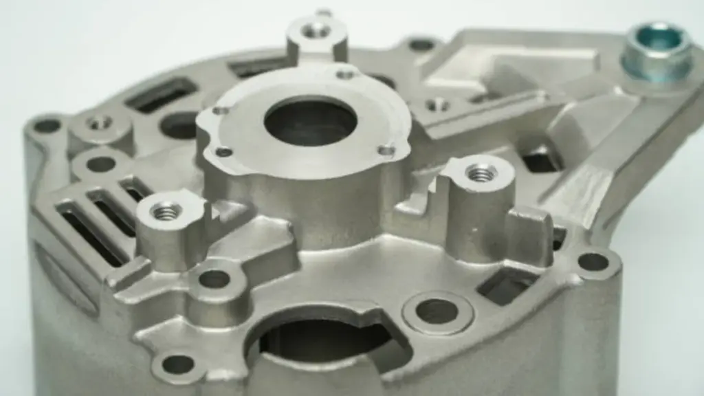
Best Materials for Hot Chamber Casting: Zinc and Magnesium Alloys
Material selection in hot chamber casting is dictated by equipment thermal limits, favoring low-melting-point alloys to ensure production speed and protect critical machine components.
Zinc Alloys (Zamak Series) for High-Speed Production
Zinc alloys are the primary material for hot chamber die casting. Their low melting point of 420°C drastically reduces thermal stress on the gooseneck and other submerged components, enabling rapid cycle times and extending die life to over 1,000,000 shots. This exceptional fluidity allows for the consistent production of complex parts with thin walls and a high-quality surface finish. Standard industry options include Zamak 3, a general-purpose alloy valued for its dimensional stability, and Zamak 5, which provides greater tensile strength for more demanding automotive applications.
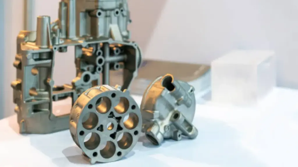
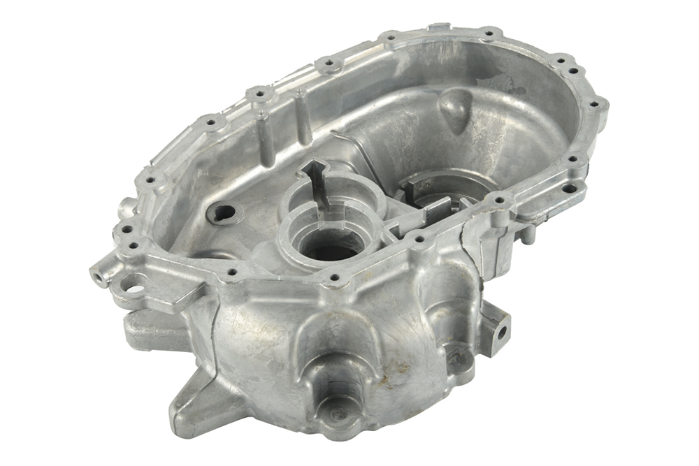
Magnesium (AZ91D) for Lightweight Structural Parts
Magnesium offers an excellent strength-to-weight ratio, making it a critical material for mass reduction in automotive and electronics components. Its melting temperature is compatible with the continuous immersion of specialized hot chamber feed systems, though it demands more careful process control than zinc due to its reactivity. The AZ91D alloy is the most specified grade for die casting, known for its balanced combination of castability, strength, and corrosion resistance in the final part. It delivers robust, lightweight components directly from the casting process.
Process Limitations Define Material Selection
The core design of a hot chamber machine restricts material choice. The gooseneck and plunger system are directly submerged in the molten metal bath, a condition that only low-melting-point alloys can tolerate without causing rapid equipment failure. Attempting to cast high-temperature metals like aluminum would destroy the steel gooseneck mechanism. The lower melting points of zinc and magnesium are not just a preference; they are a fundamental requirement for maintaining equipment longevity and ensuring the process stability needed for high-volume manufacturing.
Cut Costs with IATF-Certified Die Casting
Top Advantages: Cycle Time, Cost Efficiency, and Tooling Life
For high-volume manufacturing, hot chamber casting directly translates to faster cycle times, lower operational costs, and extended tooling lifespan due to its integrated, automated design.
Accelerated Production with Automated Molten Metal Feed
Hot chamber die casting for zinc and magnesium alloys uses an integrated furnace with a “gooseneck” system that directly and automatically delivers molten metal to the injection mechanism. This design completely eliminates the manual ladling step required in cold chamber casting, shortening per-unit cycle times by 25-40%. The result is a much faster production rate, often averaging 15 cycles per minute for high-volume components.
Strategic Cost Reduction via Global Manufacturing Layout
Bian manage initial investment costs by developing and prototyping all tooling at our technology center in China. Once the tooling is perfected, we shift mass production to our facilities in Vietnam or Mexico. This global layout allows clients to leverage tariff advantages, particularly for parts destined for North American and European markets. This “China + 2” model provides supply chain resilience and directly reduces landed costs by optimizing for both tooling investment and import duties.
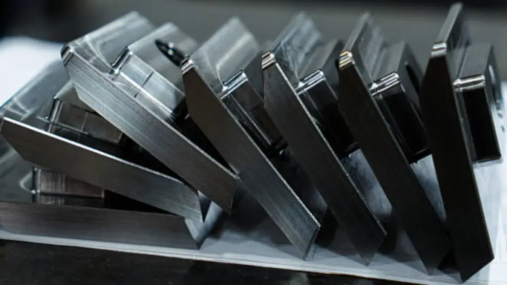
Maximizing Tooling Longevity and IP Security
Hot chamber casting inherently extends tooling life. The process uses low-melting-point alloys like Zamak 3 and Zamak 5, which operate at lower temperatures and create less thermal stress on the molds. Our tools, engineered from high-grade H13 steel at our China R&D facility, are designed for extreme durability. For zinc alloy parts, this can mean a tool lifespan exceeding 1,000,000 cycles, significantly lowering long-term production costs.
We protect this investment and your intellectual property with a centralized tooling management system. This system guarantees that performance and part quality remain identical, whether production occurs in China, Vietnam, or Mexico. Our IATF 16949-certified quality standards and strict IP protocols ensure your designs are consistent and secure across our entire global network.
Essential Design Guidelines for Hot Chamber Parts
Proper hot chamber part design leverages low-temperature alloys and high injection pressures to produce complex, thin-walled components with rapid, repeatable cycles.
Alloy Selection for Process Compatibility
Material selection is the foundational constraint in hot chamber die casting. The process is engineered exclusively for low-melting-point alloys that will not degrade the machine’s submerged gooseneck system. Specify zinc alloys like Zamak 3 and Zamak 5, or magnesium alloys such as AZ91D. These materials operate at temperatures the equipment can handle continuously, enabling the rapid cycling that defines the process. High-temperature alloys, particularly aluminum, are incompatible. The intense heat required for aluminum would damage the gooseneck, plunger, and nozzle, leading to premature failure and operational downtime.
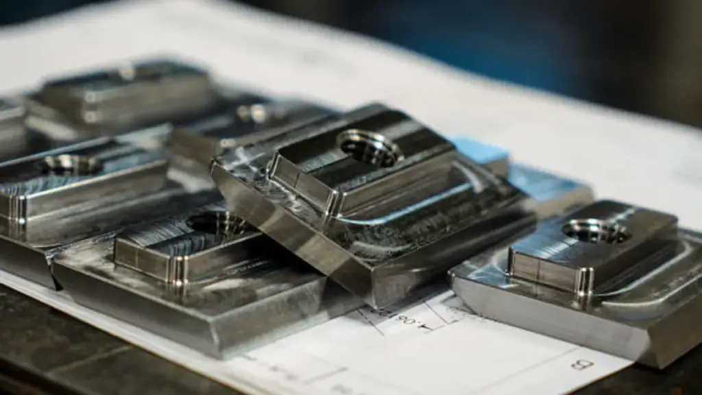
Optimizing Wall Thickness and Part Complexity
Hot chamber machines utilize high injection pressures, typically between 5 and 35 MPa, to force molten metal into the die. This capability allows for the design of parts with extremely thin walls—down to 0.8 mm with zinc alloys—and intricate, net-shape geometries that require minimal secondary machining. To maximize this advantage and prevent defects, maintain a uniform wall thickness across the part. Consistent thickness ensures rapid and even solidification, which is critical for preventing porosity, sink marks, and internal stresses. Abrupt changes in cross-section should be avoided; if necessary, use gradual transitions to maintain stable metal flow and cooling.
Designing for Efficient Metal Flow and Ejection
Successful part ejection and complete cavity filling depend on features that facilitate metal flow and release. Incorporate generous draft angles, with a minimum of 2 degrees on surfaces parallel to the die opening, to ensure the part ejects cleanly without dragging or distortion. Use fillets and radii to eliminate sharp internal corners, which can cause stress concentrations and impede metal flow; a minimum internal radius of 0.4mm is a reliable baseline. Plan gate locations strategically to leverage the direct injection path from the gooseneck, promoting a complete and consistent fill of the die cavity and reducing the risk of defects like cold shuts or misruns.
Common Defects in Hot Chamber Casting and How to Prevent Them
Controlling key process variables is the most direct way to prevent common casting defects, protecting both part integrity and the profitability of high-volume runs.
Defect: Cold shuts, misruns, and flow marks
These surface flaws happen when molten metal cools too early or meets itself without fully fusing, leaving visible lines, incomplete fill, or poor surface texture.
How to prevent it
- Increase and stabilize injection speed and fill pattern so the cavity fills before the melt loses heat
- Control die temperature in a stable window (commonly 180∘C–280∘C, tuned by part geometry and alloy)
- Optimize gate location and gate size to reduce premature freezing at thin sections
- Apply die lubricant correctly (too little increases sticking; too much can create gas-related defects)
Defect: Blisters and surface bubbling
Blisters usually appear after ejection or during finishing when trapped gas expands, or when local overheating and contamination disrupt the surface layer.
How to prevent it
- Reduce gas entrapment through better venting and overflow design
- Avoid excessive die spray/lubricant and ensure it fully flashes off before the next shot
- Keep melt temperature and die temperature consistent to avoid localized overheating
- If secondary operations (baking/painting) are planned, validate porosity limits early with sample trials
Defect: Gas porosity (internal voids)
Gas porosity weakens the part and can cause leaks, thread failure, or cosmetic problems after machining/plating. It typically comes from air trapped during fast filling, lubricant volatilization, or poor venting.
How to prevent it
- Add/clean vents and overflow wells to give air a controlled escape path
- Use an appropriate intensification phase—maintain sufficient final pressure (often within 5–35 MPa depending on machine/part) to compress residual gas
- Improve fill balance (runner symmetry, gate position) to reduce turbulence and air entrapment
- Control melt quality and housekeeping (dross removal, stable melt temperature)
Defect: Shrinkage porosity and sink marks
Shrinkage-related defects occur when metal solidifies and contracts, but the feeding path freezes too early—common around thick sections, bosses, and abrupt wall changes.
How to prevent it
- Keep wall thickness as uniform as possible; transition thickness gradually where changes are unavoidable
- Use ribs instead of thick walls to maintain stiffness without creating hot spots
- Ensure the gate stays “alive” long enough for packing (gate sizing + proper intensification timing)
- Balance die cooling so thick areas do not stay hot while thin areas freeze first
Defect: Thermal cracking and hot tearing
Cracks form when parts experience high thermal gradients or stress concentrations during solidification and ejection—often worsened by sharp corners and uneven cooling.
How to prevent it
- Add fillets and radii to remove stress risers (a practical baseline is an internal radius of at least 0.4 mm, adjusted for size)
- Avoid sharp internal corners and sudden section changes
- Stabilize die temperature and cooling layout to reduce thermal shock
- Confirm ejection strategy (draft angles, ejector placement) to avoid overstressing the part during release
Defect: Gooseneck/nozzle wear and metal contamination (process stability issue)
In hot chamber casting, submerged components face continuous thermal and chemical exposure. Excessive wear can destabilize shot consistency and introduce contamination, which shows up as surface defects, dimension drift, or higher scrap.
How to prevent it
- Inspect and replace goosenecks/nozzles/plungers on a scheduled life cycle rather than waiting for failure
- Maintain melt cleanliness and correct operating temperature to reduce attack on submerged components
- Track shot-to-shot variation and defect rates as early warning signals (process capability monitoring)
Conclusion
Choosing between hot and cold chamber die casting comes down to your material selection and production goals. The hot chamber process excels with lower-melting-point alloys like zinc and magnesium, delivering faster cycle times, lower costs, and extended tool life. Understanding these trade-offs is key to selecting the most efficient manufacturing method for your specific components.
If you are evaluating which process best fits your project’s material and volume requirements, our engineering team can help. We provide detailed analysis to optimize your design for manufacturability across our global facilities in China, Mexico, and Vietnam.
Frequently Asked Questions
Can aluminum be used in hot chamber die casting?
No, aluminum cannot be used in hot chamber die casting. The research indicates that the gooseneck system and other submerged components cannot withstand the high temperatures required for molten aluminum, as the intense heat would cause damage.
What is the main advantage of hot chamber die casting?
The main advantage is increased production efficiency and faster cycle times. This is because the furnace is integrated directly with the injection mechanism (the gooseneck), which automatically fills the chamber with molten metal, eliminating the need for manual ladling between cycles.
Why is cold chamber used for aluminum?
Cold chamber is used for aluminum because of aluminum’s high melting point. The components of a hot chamber machine, such as the gooseneck and plunger, are submerged in molten metal and cannot withstand the intense heat of aluminum without degrading or being damaged.
What materials work in hot chamber machines?
Hot chamber machines are effective for low-melting-point alloys that the gooseneck system can handle without thermal degradation. Specific materials mentioned in the research are zinc, magnesium, lead, and tin.