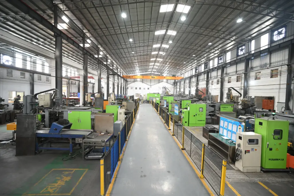
When a die cast part reaches assembly 0.15 mm out of spec, the cost is rarely the part itself. It is the stalled fixture, the rework queue, and the awkward call to your customer. Aluminum die casting tolerances are therefore decided on the drawing, long before the first shot is made. This guide focuses on the specification side: how to call out dimensional tolerances, geometric tolerances, datums, and acceptance conditions for cast and machined features.
Mag-cast’s capability pages list CNC machining tolerance down to ±0.02 mm, and machine envelopes vary by center. Machine types and envelope claims are listed on the CNC machining category page. Those figures describe what a well-run process can reach, not what every feature on your drawing should demand. The sections below turn that distinction into specification rules you can apply to your next RFQ.
Why Tolerance Specification Matters More Than Precision
Separate features that remain as-cast from those that require machining. Either group may include mating or functional surfaces. The required fit, geometry and surface condition determine whether the agreed as-cast capability is sufficient.
As-cast features inherit everything the high pressure process does well and everything it cannot fully control. Molten aluminum fills a steel mold in milliseconds, then shrinks as it solidifies and cools. Die thermal cycling, machine tonnage, and alloy chemistry all shift final dimensions. Published tolerance systems therefore define bands by grade and size range rather than single numbers.
Machined features behave differently. Once a casting is clamped in a machining center, the cutting tool sets the dimension. A part can leave the casting cell with a loose flange position and still deliver a tight bearing bore after finish machining. Specifying the right tolerance basis for each feature group is what separates a manufacturable drawing from an expensive one.
Cast Features and Machined Features Follow Different Rules
When you specify aluminum die casting tolerances, separate the two feature groups first. The table below lists what the drawing must define and what a buyer should confirm with the foundry for each group. Applicable bands depend on alloy, feature size, and the tolerance class both sides accept, so treat every row as a definition task rather than a lookup value.
| Feature Group | What the Drawing Should Define | What to Confirm With the Foundry |
|---|---|---|
| Wall thickness (cast) | Nominal value, limits, and draft direction | Minimum wall the die can fill for your alloy and part size |
| Cored holes (cast) | Diameter limits or a referenced tolerance class | Core shift behavior and as-cast size capability |
| Bearing bores (machined) | Fit class chosen with the bearing supplier | Boring capability and measurement method for the fit |
| Sealing faces (machined) | Flatness zone on the specified surface, plus roughness value | Fixture plan and verification method for that zone |
| Threaded holes (machined) | Thread class, depth, and position with named datums | Gauge or CMM acceptance basis before production starts |
Two patterns are worth noticing. First, finish machining typically improves a feature by roughly one order of magnitude compared with as-cast, which is why mating surfaces are machined. Second, cost grows with every feature pushed into the machined column. The engineering question is not whether a feature can be machined, but which features genuinely need it. Our aluminum die casting machining checklist covers the datum and allowance side of that decision.
How to Specify As-Cast Tolerance Requirements
Most disputes over aluminum die casting tolerances start with an incomplete general note. A citation is only usable when the drawing states the standard, the part or division, the version, and the tolerance class, along with the size range the class applies to. A bare reference without version and grade leaves the foundry to guess, and guesses differ between suppliers.
Check the current status of any standard before citing it. Several entries in the DIN 1688 series for light metal rough castings have been withdrawn or replaced, as the DIN Media listing shows. A drawing that cites a retired document invites a contract question, not just an engineering one.
Then decide what deserves an individual callout. Features that locate other components, seal fluids, or carry loads should each state their own limits and datum references. Everything else can sit under the general note. Confirm that the chosen class is inside the foundry’s demonstrated range for similar parts: ask for measurement data from real production, not a catalog figure.
Two as-cast effects deserve their own line items. Draft angles change the effective size of a wall or boss depending on where you measure, so state the measurement position. Parting-line mismatch shifts one half of the casting relative to the other. Features that straddle the parting line therefore often get tighter individual callouts, or move to the machined column. Recording both effects on the drawing is what keeps aluminum die casting tolerances from being argued after the fact.
How to Call Out Fits and Geometric Controls
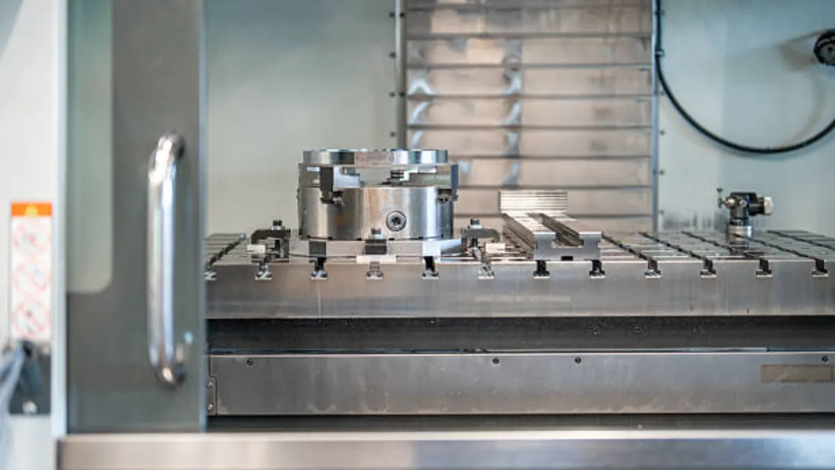
Dimensional limits alone do not control function. A ±0.05 mm box on a hole center is not the same as a true-position callout, because position tolerance depends on the datum reference frame it is tied to. When hole location matters for assembly, specify a geometric position tolerance with named datums, so machining and inspection share the same reference.
Bearing bores should follow the bearing fit, not a house number. The correct band comes from the shaft and bearing manufacturer’s fit recommendation, expressed as an ISO fit class or explicit limits. The same logic applies to pilot diameters and locating pins. Where a supplier lists a reach such as ±0.02 mm, that figure is a capability, and the drawing decides whether a feature needs it.
Flatness belongs to the surface that seals. A blanket millimeter-per-meter rule for all faces pushes cost into surfaces nobody inspects. Specify flatness and roughness on the designated sealing zone, and leave non-mating faces to the general note. Re-fixturing also deserves attention: a second setup can introduce a change in positioning, and its impact depends on the fixture, the datum scheme, and the verification results. The axis-count trade-off is covered in our 3-, 4-, and 5-axis guide.
Acceptance conditions should be agreed per feature, not by a blanket rule. A coordinate measuring machine gives variable data for critical dimensions, while go/no-go gauges remain a legitimate acceptance method for threads and many other functional features. Map each important characteristic to its measurement method in the control plan, as described on our quality control page.
Finally, think in chains rather than single callouts. A hinge with three machined bosses can hold every bore to its stated tolerance and still miss its closure dimension, because the stack runs through the casting between the bosses. Define the datum chain on the drawing, walk each link, and confirm the worst-case sum meets the assembly requirement. When it does not, tighten one or two chain links by machining instead of every dimension on the page, which multiplies cost without rescuing the stack.

What Prototype Machining Can and Cannot Prove
Production tooling takes weeks to cut, and design teams rarely want to wait that long to touch a physical part. A machined prototype, from billet or a short-run casting, closes that gap and supports early fit checks, assembly trials, and form evaluation. Our rapid prototyping service covers this stage.
Read the limits honestly. A billet prototype differs from a mass-production die casting in material, porosity, deformation behavior, and fixturing response. Prototype results can verify shape, fit, and assembly; they cannot prove the gas tightness, strength, or process capability of production die cast parts. Tests that depend on as-cast skin behavior need cast prototypes, and capability claims need production-intent parts measured under the agreed plan.
A practical sequence keeps those roles separate. Release the CAD model, take the DFM feedback on wall thickness, draft, and tolerance-stack risks, then machine prototypes to settle fit and assembly questions. Freeze the design, cut the production die, and reserve tight verification for the first production-intent articles. The expensive failure mode this ordering avoids is a mold that is metallurgically sound but slightly off on the face that mates with a purchased component.
Tolerance Specification Checklist for Your Next RFQ
Before requesting a quote, run your drawing through the table below. It compresses the rules above into items you can decide at your desk, and fewer open questions come back across the table during quotation. The goal is not to make every number tight. The goal is to make every number intentional, so the supplier prices the function you actually need.
| Drawing Element | Requirement to Define and Confirm | Why |
|---|---|---|
| General tolerance note | Standard, part, version, class, and applicable size range | Retired or vague citations cause disputes |
| Mating features | Individual limits with named datum references | Location and function need their own control |
| Sealing surfaces | Flatness zone and roughness on the specified area | Seals depend on the zone, not the general note |
| Threads and gauged holes | Thread class plus the agreed gauge acceptance basis | Gauges are valid acceptance for functional features |
| Prototype scope | What the prototype must prove and what it will not | Prevents false confidence before tooling |
Ask for a DFM review before the drawing freezes. Mag-cast provides a free DFM analysis report, with quotes in two days and DFM in three days per our published service terms. Our pre-quote DFM checklist shows what such a review should cover.
Questions About Die Casting Tolerance Specification
What tolerance can aluminum die casting hold without machining?
There is no single number. As-cast bands depend on alloy, feature type, size range, and the tolerance class of the standard both sides accept. Agree the standard, version, and class on the drawing, then confirm the foundry’s demonstrated capability with measurement data from similar production parts rather than catalog claims.
Can prototype results predict production die cast tolerances?
Only partly. Machined prototypes verify shape, fit, and assembly early. They cannot prove the gas tightness, strength, or process capability of production die castings, because material, porosity, and fixturing behavior differ. Use short-run castings for skin-dependent tests and production-intent parts for capability evidence.
Why does a tighter tolerance raise the price?
Tight callouts change the process, not just the number. They add machining passes, careful workholding, thermal management, and slower inspection. The cost is justified on functional features and wasted on non-mating surfaces, which is why tolerance discipline on the drawing controls piece price directly.
Which standard should I cite for as-cast tolerances?
Cite a current document both parties accept, and state its part, version, and tolerance class on the drawing. Verify the status first: several DIN 1688 entries for light metal rough castings have been withdrawn or replaced. When no single standard fits, define per-feature limits with named datums instead.
Final Thoughts
Aluminum die casting tolerances are the acceptance language of your drawing. The foundry can reach tight numbers; the buyer’s job is to say which features must be tight, against which datums, verified by which method, and under which standard. Write that down and quotes become comparable, first articles stop surprising, and precision is spent only where function needs it.
Start with the features that mate, seal, or carry load. Define their tolerances, geometric controls, and acceptance conditions explicitly, and let everything else ride on a complete general note. Send your drawing through the contact page and ask for the review before tooling starts.