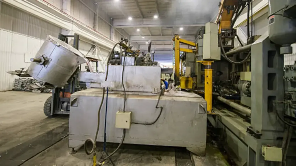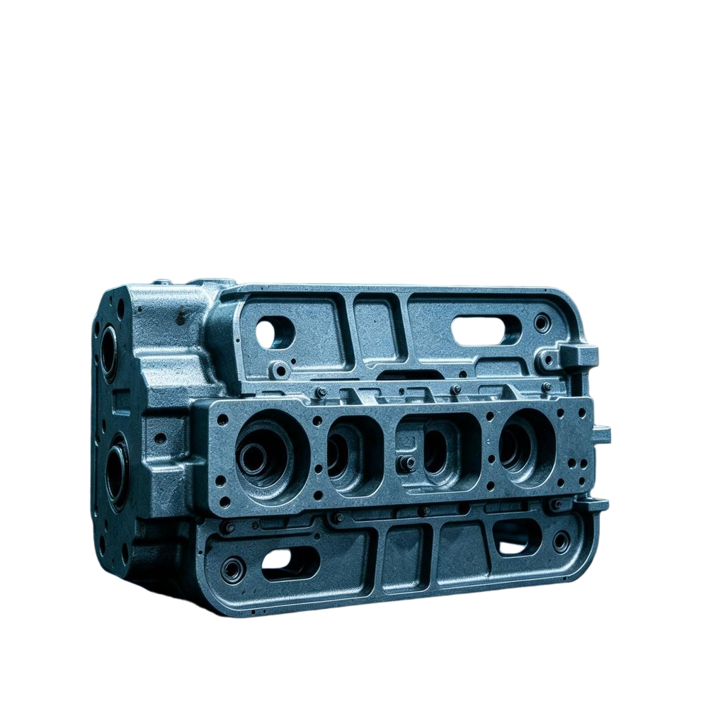
Porosity in die cast light housings can create leak paths, weaken local features and cause surface flaws that become visible after machining or finishing. Tracing the root cause early helps buyers lower the risk of water ingress, rework and field returns.
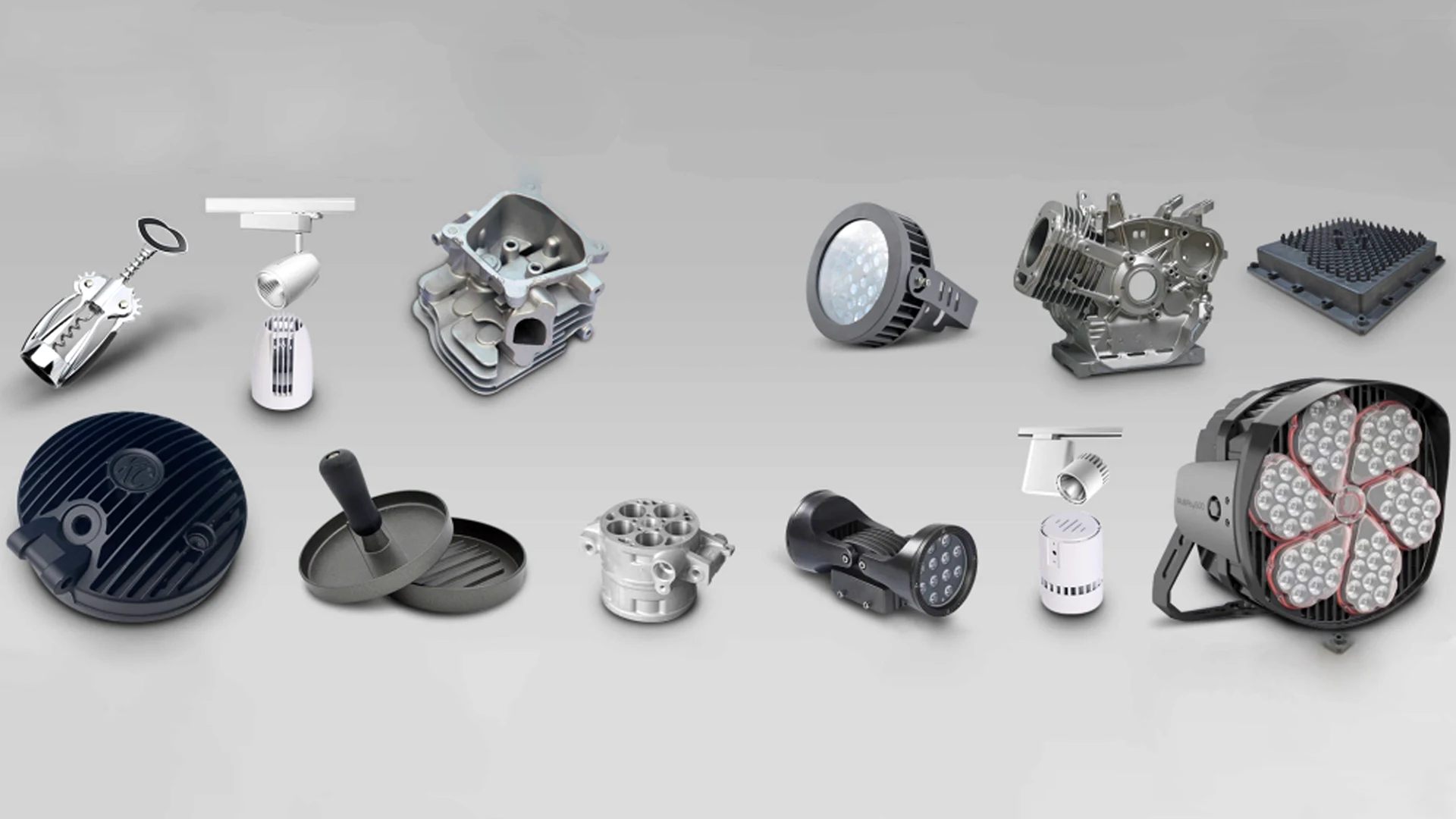
This article explains why voids form in housings, how gas and shrinkage porosity differ, and which design and melt controls matter. It also reviews inspection methods and lists the checkpoints a buyer should verify with a supplier before tooling. These apply to the LED street, flood and track light housings shown in our lighting parts catalog.
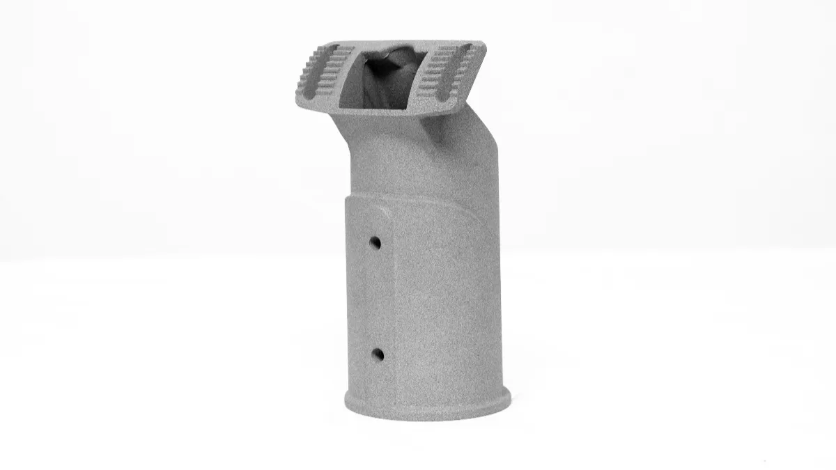
Why Porosity Happens in Die Cast Light Housings
Porosity in die cast light housings stems from trapped gas, solidification shrinkage, and melt contamination. Understanding these root causes helps buyers and engineers target the right controls.
| Defect Category | Primary Trigger | Typical Appearance in Sections |
|---|---|---|
| Gas Porosity | High-speed turbulent flow and blocked vents | Smooth, rounded internal voids |
| Shrinkage Porosity | Uneven cooling in variable wall thicknesses | Irregular, sponge-like cavities in thick sections |
Gas Entrapment During Metal Filling
High-pressure die casting pushes molten metal into cavities at extreme speeds. When this flow becomes chaotic, it captures surrounding air before the air can exit the mold.
- High-speed molten metal flow can tumble or fold over, trapping air in blind corners or behind deep heat sink fins.
- Inadequate venting or blocked vacuum channels prevent air from escaping, leaving residual gas bubbles within the housing.
- Excessive die lubricant or moisture on the die surface flashes into steam upon metal contact, generating gas cavities.
Solidification Shrinkage in Variable Wall Thicknesses
As liquid metal cools, it naturally contracts. Light housings often mix thin fins with heavy mounting points, creating thermal imbalances during this cooling phase.
- Aluminum and magnesium alloys undergo natural volume contraction as they cool and solidify.
- Thick sections, such as mounting bosses and hinge lugs, retain heat longer and freeze last, creating localized shrinkage hot spots.
- Uneven cooling between thin fins and heavy structural areas blocks the feeding of liquid metal, resulting in central shrinkage voids.
Oxide Inclusions and Melt Contamination
The quality of the molten metal directly impacts the structural integrity of the final casting. Poor melt management introduces foreign particles that disrupt the metal matrix.
- Natural oxide films on the aluminum melt can fold into the casting during highly turbulent flow phases.
- Re-melting uncleaned scrap or gating returns introduces solid inclusions that disrupt metal flow.
- Inclusion-related defects can compromise sealing if they intersect a machined sealing surface or form part of a connected leak path.
Tooling Wear and Process Mismanagement
Even with a sound part design, degraded equipment and incorrect machine settings can ruin production runs. Maintaining control over die condition and process parameters prevents spontaneous defects.
- Eroded die surfaces and flashing can alter optimal metal flow paths and obstruct vital air vents.
- Cold spots in the die cause premature freezing, while excessively hot zones delay solidification and increase shrinkage risk.
- Incorrect shot speed or pressure settings fail to drive air out effectively, leading to cold shuts or excessive turbulence.
How Gas and Shrinkage Porosity Differ in Practice
Gas porosity stems from trapped air and leaves smooth voids. Shrinkage porosity results from unfed metal contraction and creates irregular cavities. Reading both evidence types guides the corrective focus.
Visual Characteristics and Defect Locations
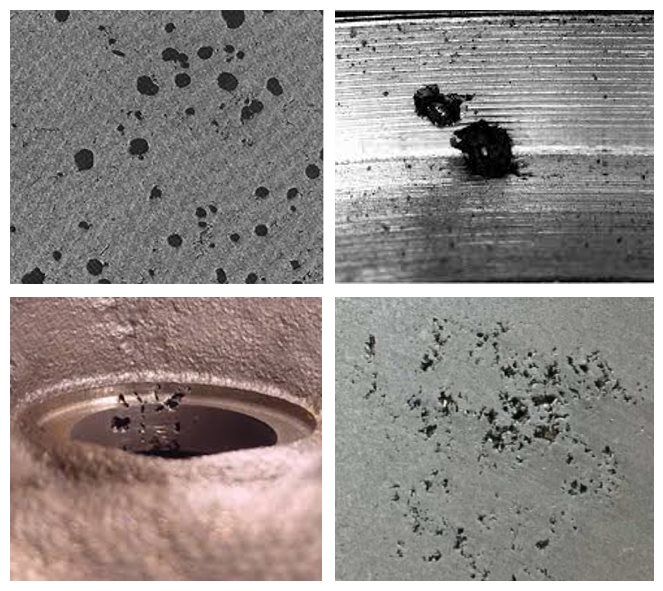
The two types often show different shapes and locations. Gas voids tend to appear as rounded bubbles with smooth internal surfaces, clustered near the skin, thin walls, or end-of-fill regions. Shrinkage voids look irregular and dendritic, with rough textures, and they concentrate in heavy sections that cool last.
These patterns are tendencies, not proof. Real parts can mix both types, and oxide inclusions add a third pattern. Confirm the diagnosis with cross-sections and process records before agreeing corrective actions with a supplier.
Process Variables and Diagnostic Indicators
Gas defects are commonly linked to turbulent filling, blocked vents, wet charge materials, and excessive die spray. Reviewing the shot curve and the vent condition usually points to the contributing factor.
Shrinkage defects are commonly linked to insufficient holding pressure, short hold times, and unbalanced die temperatures. On radiographs, both types appear as darker areas, and image shape alone does not separate them. Experienced foundries combine the image, the defect location, sectioning, and the process log before naming the cause.
Impact on Part Performance and Repair Options
Trapped gas expands inside powder-coating cure ovens, so pinholes and blisters appear on finished surfaces. Machining can open subsurface voids and turn them into leak paths at gasket grooves and bores. Surface finishing does not hide porosity, because coated and anodized parts can still reveal subsurface voids as visible marks.
Vacuum impregnation can seal internal, interconnected leak paths once the part is approved for it, and sealed castings are re-tested for leakage. It is not a surface treatment, and it does not repair cracks or large shrinkage cavities. Structural fixes still come from gating, cooling and feeding design.
Why Wall Thickness and Flow Design Increase Risk
Unbalanced wall thickness and erratic flow paths act as the primary structural drivers of porosity. Thin sections freeze prematurely, trapping air, while thick masses create isolated shrinkage hot spots.
The Impact of Excessive Wall Thickness
Housings mix thin cooling fins with thicker mounting features, and each zone cools at its own speed. There is no single wall thickness where the process behavior suddenly changes. The risk grows as local mass increases and slows solidification in that region.
A thick zone that freezes last needs liquid metal feeding long after the surrounding walls have closed. When that feeding is blocked, shrinkage voids form in the core. Buyers should expect heavy sections, bosses and rib junctions to be flagged during the DFM review of die cast light housing drawings.
How Non-Uniform Walls Create Hot Spots
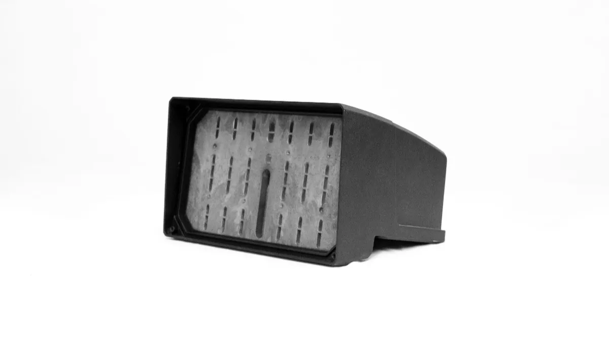
Sudden jumps in thickness, such as a thin wall feeding directly into a boss several times thicker, create localized thermal hot spots. The surrounding thin sections shed heat rapidly and freeze first.
That premature freezing acts like a dam, cutting off metal feeding to the adjacent thick area and leaving internal voids. Solid bosses, heavy back walls, and dense rib clusters need gradual transitions and coring, especially where later machining will expose the surface.
Flow Design Flaws and Air Entrapment
How the machine pushes metal into the cavity matters as much as geometry. A poorly placed gate can make metal jet across the open cavity, folding air into the flow front. Long runs through alternating thick and thin zones create unbalanced fill and pressure swings.
To solve cold shuts, some teams add local thickness instead of fixing the gate layout. That usually backfires, because the added mass becomes a new hot zone. Keeping the cross-section steady along the main flow path holds the metal front uniform and vents air ahead of it.
How Melt Quality and Alloy Control Affect Porosity
Poor melt quality and off-spec alloys multiply gas bubbles and shrinkage voids. Controlling hydrogen, oxides, and the silicon balance matters for leak-tight, structurally sound housings.
Melt Cleanliness and Hydrogen Control
Hydrogen dissolves easily into molten aluminum and precipitates as the metal solidifies, leaving fine gas pores. Common foundry controls include using dry primary ingots, limiting dirty return scrap, and degassing the melt with inert gas before casting.
Filtration serves a different purpose. It traps suspended oxides and inclusions, so they cannot seed defects or block feeding. Degassing and filtration are complementary, and both belong in the process documentation a buyer reviews. Temperature discipline limits further hydrogen pickup during holding.
Alloy Chemistry and Solidification Dynamics
The alloy chemistry decides how the metal feeds and freezes. Silicon content governs fluidity and shrinkage behavior, so foundries set working limits that balance thin-wall filling with mechanical properties.
Confirm alloy chemistry against the specified material standard, including silicon, iron and other controlled elements. Any alloy change or melt treatment should be validated for the housing’s filling behavior, casting soundness and required properties.
Impact on Light Housing Performance
Melt quality failures surface later as leaks, cosmetic rejects, or early fatigue. Clean, dense metal holds pressure at machined sealing surfaces and keeps finishing yields high. Gas expansion during powder-coating cure shows up as blistering and pinholes on visible faces.
Casting soundness and luminaire protection are separate checkpoints. A housing can pass its own leak test while the assembled lamp still fails, because gaskets, lens interfaces and fasteners also set the sealing performance. The IP code is the enclosure protection rating system defined by the IEC 60529 standard, and the finished luminaire must be verified as an assembly.

Machined and finished surfaces can also reveal subsurface porosity as gray marks or open pits. This is why housing buyers agree cosmetic and tightness limits before selecting the finishing route.
Which Inspection Methods Detect Porosity Before Shipment
A layered inspection strategy pairs baseline screening, such as visual and leak checks, with radiographic sampling. Frequencies follow the control plan agreed with the customer.
No single method finds every void, and detection ability depends on lighting, magnification, surface condition and the acceptance limits written into the control plan. The table below summarizes the methods most relevant to die cast light housing programs.
| Method | What It Can Show | Typical Use for Housings |
|---|---|---|
| Visual or AOI | Surface pores on external faces and gasket seats | Baseline screening with agreed viewing conditions |
| Dye penetrant | Void openings that reach the surface | Detecting surface-breaking discontinuities after machining; it does not confirm a through-wall leak path |
| Pressure decay or helium test | Connected leak paths through the wall | Leak checks on sealing-critical parts per plan |
| 2D X-ray | Projected indications of internal voids, subject to overlap and image resolution | Sampling checks guided by reference images |
| 3D CT scan | Pore volume, size and distance to features | First-article studies and failure troubleshooting |
ASTM E505 reference radiographs can support evaluation of aluminum and magnesium die castings within their applicable scope. Buyers and suppliers should agree the inspection regions and acceptance criteria for the part.
When a part fails, first rule out fixture leakage and other sealing defects. Use targeted imaging or sectioning where needed to investigate the casting. The equipment and methods we run in house are described on our leak detection capability page.
What Buyers Should Confirm With Suppliers
Process claims deserve evidence. These are the checkpoints a buyer can verify during audits, trial runs and documentation review before committing to tooling.
Gating, Venting and Filling Controls
Ask how the die manages filling. Predictable gate design, vents and overflows at last-to-fill areas, and controlled shot profiles reduce jetting and air entrapment. High-integrity programs may use vacuum-assisted filling, and we explain where it fits in our vacuum die casting guide.
Melt Handling and Alloy Documentation
Ask for the degassing and filtration practice, and check that the records separate dissolved-hydrogen control from inclusion removal. Request the exact alloy grade and its material standard. A380 and ADC10 come from different standard systems, so specify the grade actually used instead of assuming equivalence.
Process Monitoring and Inspection Evidence
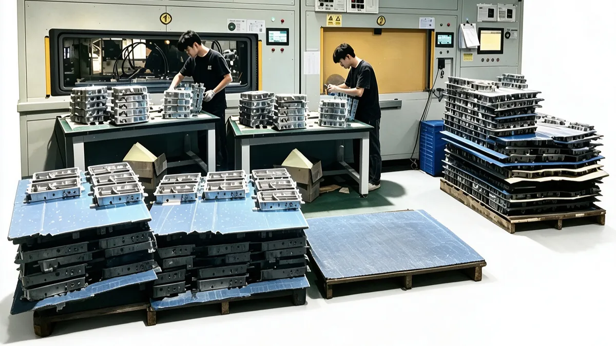
Ask which machine parameters are logged, how deviations trigger a reaction, and whether the plant keeps a verified reference setup for comparison. Then confirm which inspection devices are physically on site. X-ray access is common in die casting plants, while CT or ultrasonic capability should be verified rather than assumed.
Certifications, Documents and Post-Casting Options
IATF 16949 suits automotive programs, and this site lists PPAP, APQP, FMEA and similar documents on request. A certification scope does not prove specific equipment, so verify capabilities during an audit or a pilot run.
For leak-critical castings, ask whether vacuum impregnation is available and how sealed parts are re-tested. Impregnation closes approved internal leak paths; it does not repair cracks or replace luminaire-level sealing verification.
Questions About Die Casting Housing Porosity
What causes porosity in die cast light housings?
Three mechanisms dominate. Turbulent filling traps air, dissolved hydrogen precipitates during solidification, and thick sections shrink without enough liquid feeding. Dirty melt, blocked vents, worn dies and unstable settings make all of them worse. Light housings add risk because thin fins and heavy bosses sit millimeters apart.
Can porosity cause water leakage in an outdoor luminaire?
It can, when voids connect through the wall or machining opens them at a gasket seat. That is why sealing-critical zones get leak tested. The housing passing its own test does not replace the IP verification of the assembled luminaire with its lens, gaskets and cable glands.
How should porosity be inspected before shipment?
Pair surface screening, such as visual checks or dye penetrant, with internal methods like X-ray sampling, and add leak testing where sealing matters. The agreed control plan sets frequencies and acceptance limits for the program, based on part risk and customer requirements.
When does vacuum impregnation help a housing?
Impregnation can seal internal, interconnected leak paths once engineering approves the part, and sealed castings are re-tested for leakage. It is not a surface treatment, and it cannot fix cracks or restore large shrinkage cavities. The Godfrey & Wing article explains which leak paths seal.
Final Thoughts
Porosity in die cast light housings becomes manageable when its causes are understood early. Buyers gain the most from three habits. Review heavy sections and flow design during DFM, and agree the control plan and acceptance limits in writing. Then verify supplier process claims with audit evidence or pilot data.
Before committing to tooling, share your housing drawings, sealing requirements, alloy preference and finishing plans through our contact page. The free DFM analysis report notes risk areas such as heavy sections and flow paths, and quotations return within two days. You can also review our full range of services on the home page.