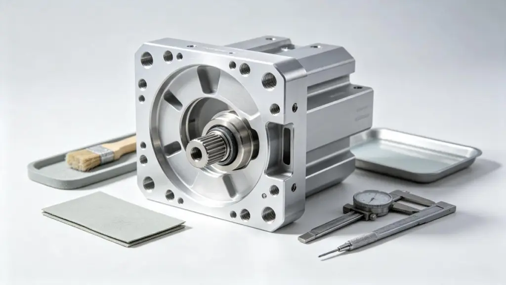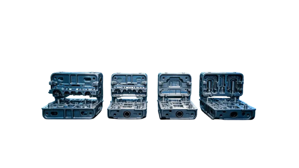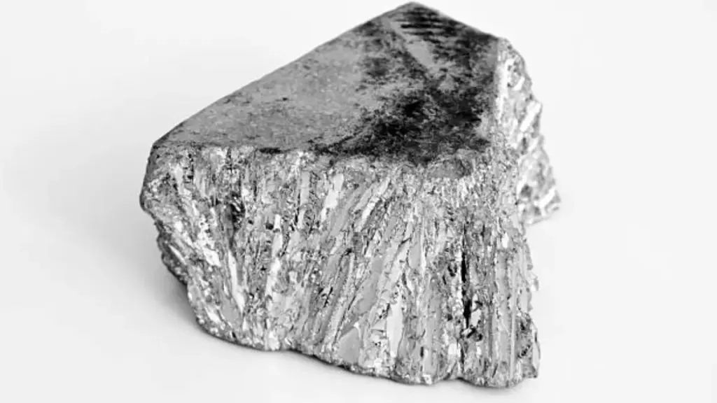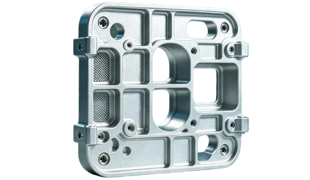
A die casting leaves the machine remarkably close to finished: forme nette, parois minces, and integral ribs produced in one fast cycle. Close is exactly the problem on the features that matter. The hole a bolt threads into and the bore a bearing sits in are not trustworthy straight off the casting machine. Neither is the flat face a gasket seals against, nor the bosses that locate a subassembly. Those features arrive dimensionally approximate, softly edged, and coated in process residue. Post machining is the cutting work done after casting to bring selected features to drawing tolerance. It is the stage that turns a net-shape part into one that assembles.
Knowing why post-machining exists and which operations do what is one skill. Designing a part so it machines cleanly afterward is another. Together they separate a program that ramps smoothly from one that spends months fighting tolerance creep. This guide covers the operations, the tolerance gap between the two processes, and the design habits that keep secondary work cheap. The machining process from casting to finished part is summarized in this site’s CNC machining explainer.
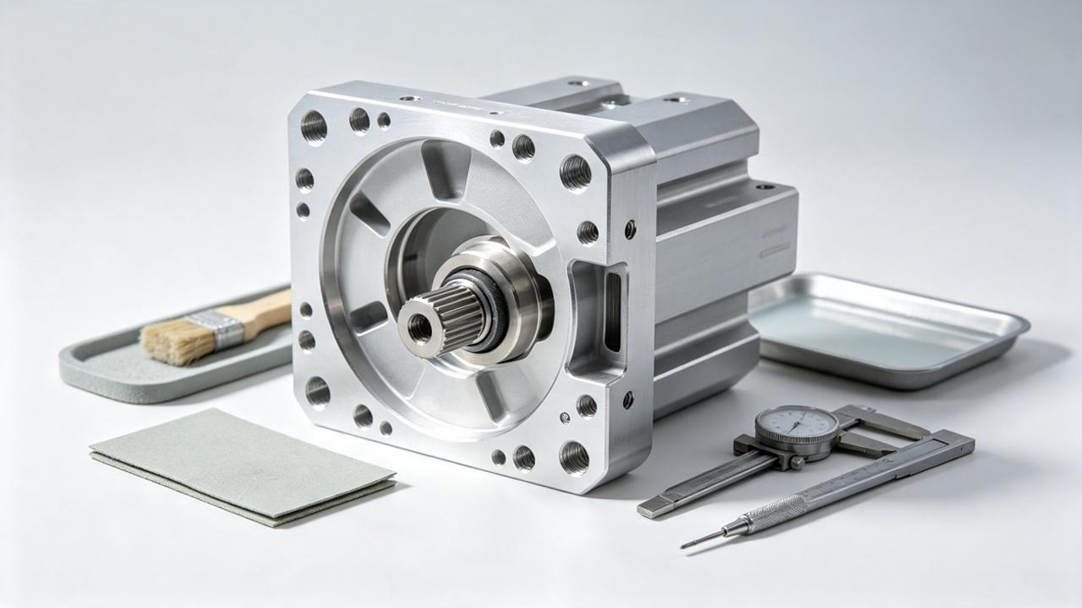
What Post Machining Means on a Die Casting
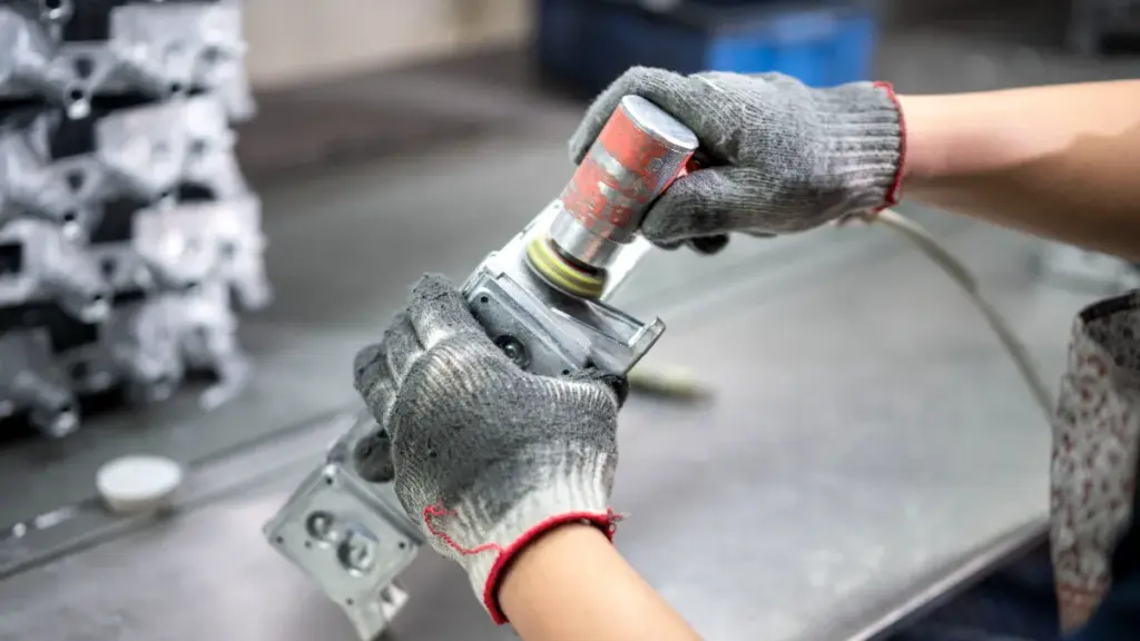
Post machining is any subtractive operation performed after the part leaves the die: forage, tapotement, fraisage, ennuyeux, alésage, counterboring, countersinking, and punching. It sits between casting, or casting and a blasting step, and final assembly in the process chain. It exists because two different physics govern the two stages. Die casting excels at forming complex geometry fast in three dimensions. Machining excels at holding a small number of dimensions tightly. A single part legitimately uses both, and the drawing’s job is to mark which is which.
The confusion that sinks programs is treating the casting as the finished part everywhere, or machining as a replacement for good casting design everywhere. The first gives leaky threads and wobbly bearings. The second pays cutting rates for geometry the die could have formed for free. The right question for every feature is not whether it can be machined. It is which tolerance the feature actually needs and whether the die can deliver it.
Why the As-Cast State Falls Short
Four limits of the die-casting process create the work list for the machining stage. First is dimensional drift. As-cast dimensions sit within a casting tolerance class, on the order of a tenth of a millimetre on typical part sizes and looser on large, thermally active areas. That is generous compared with a fit or a thread. Second is surface quality on formed faces. As-cast surfaces carry flow lines and vent witness marks, and their roughness varies with alloy and die condition. A machined face resets to the smoother, flatter profile left by the tool path.
Third is feature integrity. Holes cast against the metal flow arrive with slight ovality and soft burr edges, and cast threads are not specified because real threads are cut or formed. Fourth is release and draft. Every die feature needs draft angle so the part can eject, which is precisely what a flat gasket face or a square-cornered counterbore does not want. Machining resolves exactly these cases. It creates true round bores, flat sealing faces, clean threads, and square internal corners the die cannot release from.
Common Post Machining Operations and What Each Solves
| Opération | What It Produces | Why It Is Machined, Not Cast |
|---|---|---|
| Forage | True-position round holes | Cast holes ovalize and drift from the drawing position |
| Tapotement | Load-bearing internal threads | Cast threads strip; torque specs need cut thread forms |
| Fraisage | Plat, smooth faces and pockets | Gasket, mating, and datum surfaces need flatness draft cannot give |
| Ennuyeux / alésage | Precision-diameter bores | Bearing seats and pin bores fit on the bore, not the cast pilot |
| Counterboring / spotfacing | Flat seats for bolt heads and washers | Fastener preload needs a square bearing face, not a drafted one |
| Engraving / punching | Part marks, serials, vent holes | Traceability and late-stage geometry the die should not carry |
The economic logic reads straight off the table. Every machined feature is a tolerance promise the die cannot make. A program that machines everything pays for the promise twice. One that machines nothing skips that cost, then meets the bill at assembly.
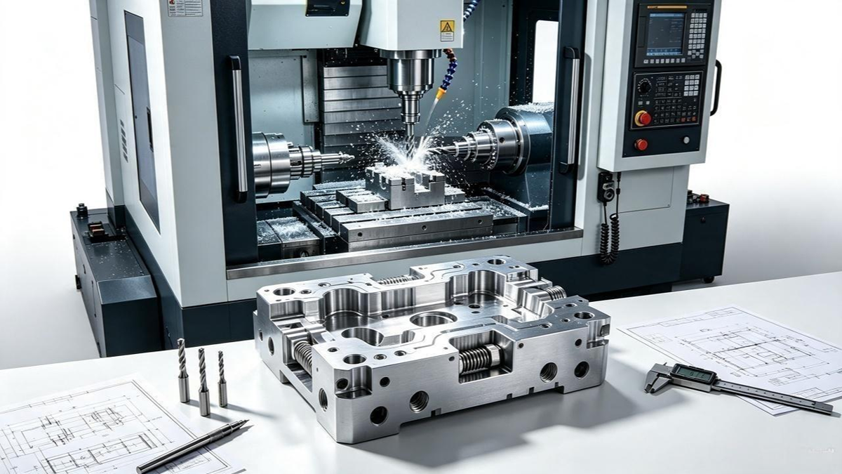
The finishing operations that follow machining, from deburring to coating, sit in a separate stage with its own checklist. This site’s post-machining finishing page describes how those steps are sequenced after the cutting work covered here.
The Tolerance Gap Between Casting and Machining
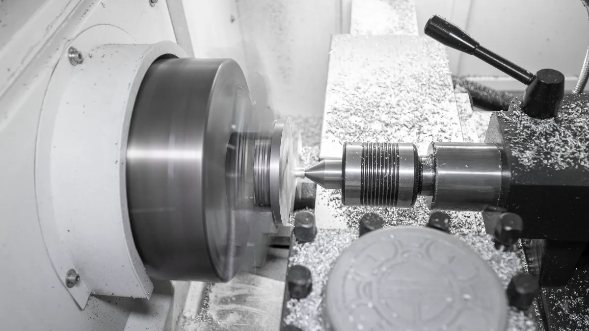
The practical rule is that die casting holds dimensions in tenths of a millimetre, good and predictable but not fit level. Routine machined fits are commonly held in the hundredths. Standards draw the same line. As the reference work Geometrical Dimensioning and Tolerancing notes, general tolerances follow ISO 2768 for metallic machined parts and ISO 8062-3 for castings, two separate systems for two separate processes.
That gap is roughly an order of magnitude, and it is why the drawing must state which side of the line each feature lives on. The boss the die forms is casting tolerance. The bore inside it is machining tolerance. Confusing the two is how either money or function gets lost. A buyer comparing quotes should confirm the tolerance class named for each critical feature rather than assuming the tighter number applies everywhere.
How those classes get written onto a drawing is its own discipline. Le guide de specifying cast and machined tolerances on this site covers datum callouts and the tolerance grades a die can realistically hold.
Designing the Casting to Be Machined
Parts that machine well are designed for it before the die is cut. Four habits carry most of the payoff. First is machining stock. A critical face that will be milled should cast high enough to give the cutter real material to remove. A hundredth or two of stock lets it level out the as-cast irregularity instead of chasing it. Second is datum logic. The part needs a clean, defined reference surface or bore for the fixture to locate against on every setup, and the drawing should name which feature is the datum.
Third is rigidity where the cutter bites. Thin drafted walls spring under milling pressure, so ribs and generous fillets around machined pads keep the cut stable and the tolerance held. Fourth is tool access. Drill and tap stations need clearance above the hole and room for the cutter. Geometry that packs machined features into inaccessible corners forces multi-axis setups that could have been designed out. A pre-production liste de contrôle d'usinage is the practical way to confirm all four before the tool is cut.
The flip side also holds. Features the die can form accurately, such as bosses, côtes, locators, and draft angles, should be cast rather than machined, because casting forms them for free inside the cycle time. The design-for-manufacturing conversation between die designer and machinist happens exactly at this boundary.
The Cost Logic of Secondary Operations
Post machining cost is dominated by fixturing and setup, not by the swarf. Each time a part must be re-chucked to reach a new face, the program pays the setup, the datum error accumulated across setups, and the labor. Multi-axis capability changes that arithmetic. A four- or five-axis machining center can present several faces to the tool in one setup, holding tolerances across features that would otherwise stack their location error from separate setups.
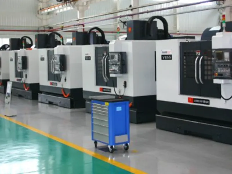
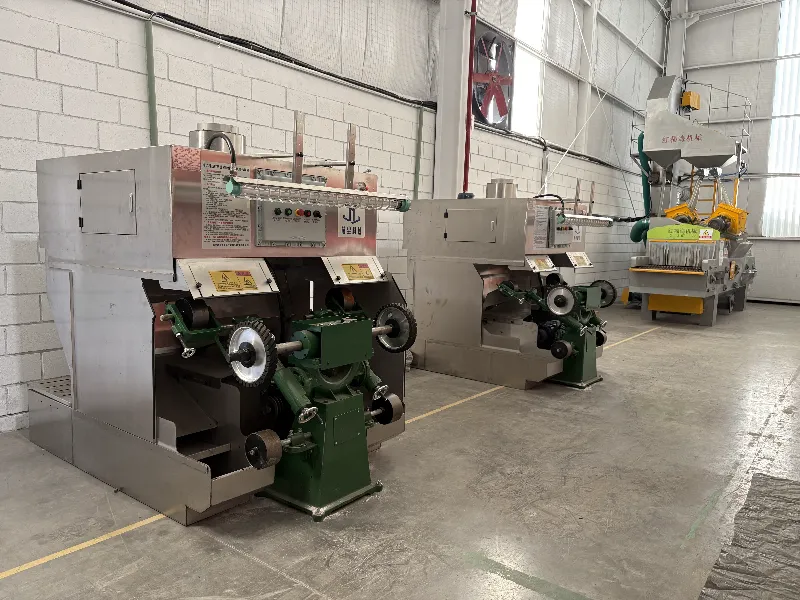
For high-volume hardware, dedicated automation often sits underneath the machining tier. Multi-function drilling units, automatic tappers, and punching machines take simple, repetitive operations off the machining centers. A pattern of four through-holes and six taps runs at rates a CNC would not match. The sensible split is usually automated stations for easy, high-count holes and CNC for anything needing accuracy, complexity, or a milled face.
Whether that split actually saves money depends on volume and feature count. The breakdown of what drives machining cost on this site compares setup, temps de cycle, and tooling. A buyer can see where secondary operations add cost and where they remove it.
Machined Features Are a Different Inspection Problem
As-cast geometry is checked against casting tolerances; machined features are checked against fit. That moves them onto different instruments. Coordinate-measuring machines and optical profile projectors verify hole positions, bore diameters, and flatness at the machining tolerance band. Threads get function-tested, including torque checks that confirm a fastener seat loads the boss rather than shearing the first turn. Sealing faces get verified with the mating gasket or an air-leakage tester, because a flatness reading that passes on the table can still leak on the assembly.
Automotive-grade work often adds a cleanliness extraction step, since swarf and coolant residue trapped in a machined blind bore are a failure the drawing did not anticipate. The practical consequence is documentation. A first-article report should pair each machined feature with the method that proves it. Use a coordinate-measuring machine for location, a bore gauge or projector for diameter, and a torque test for threads. A leak test, not one overall impression of within tolerance, proves each sealing face.
Where the Cast and Machined Boundary Is Set
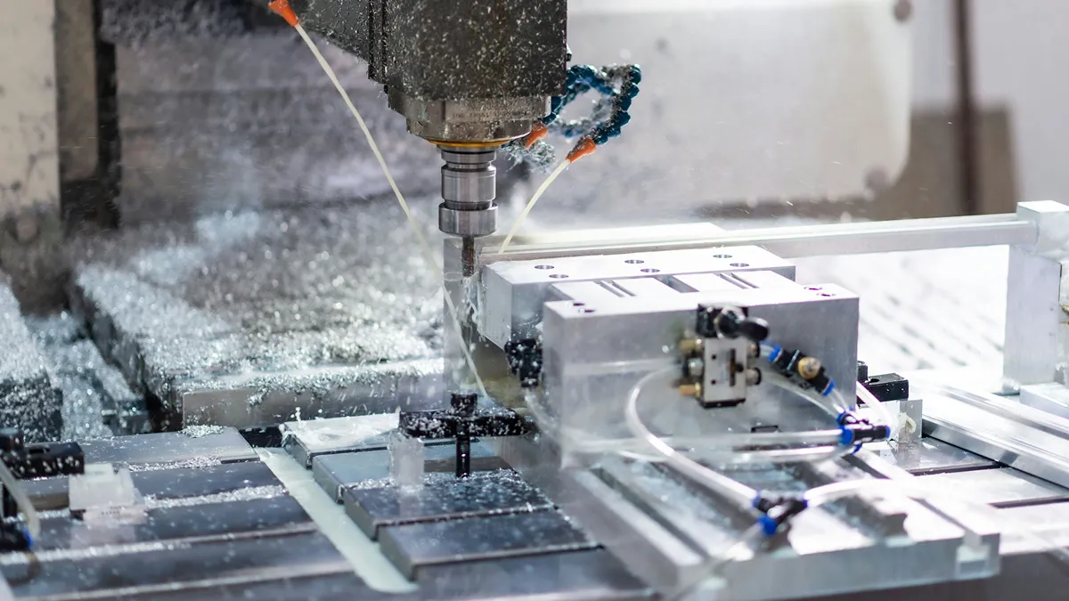
The boundary between what the die holds and what the cutter finishes is a decision, not a default, and the cheapest place to make it is during tooling design. Buyers should ask a supplier to mark, feature by feature, which dimensions carry a machining allowance and which are trusted to the as-cast tolerance class. That single pass exposes the faces that need stock, the bores that need a datum, and the corners that force an extra axis.
When casting and machining are quoted together, the boundary is set once instead of twice across a supplier handoff. Le CNC machining capability pages on this site list the tolerance and geometry envelope the shop holds, and the service description notes a free DFM analysis report with each quote.
Questions About Post Machining for Die Castings
What is post machining in die casting?
Post machining is the subtractive work done after casting, covering drilling, tapotement, fraisage, ennuyeux, alésage, counterboring, and punching. It brings selected features to tolerances and surface qualities the die cannot produce. The stage converts net-shape castings into assembly-ready parts wherever fit, scellage, or threading is required.
Why cannot die casting hold tight tolerances alone?
As-cast dimensions typically land within a casting tolerance class around a tenth of a millimetre. Bores ovalize against metal flow, draft angles prevent square internal corners, and cast threads cannot carry torque. Machining holds the same features far tighter with true roundness and flatness, closing the gap between the two processes.
Which features on a die casting should be machined?
Only the features whose function demands it. Threaded holes that will be torqued, bearing and pin bores that carry fits, gasket and datum faces that need flatness, and counterbores that seat fasteners square all justify a cut. Patrons, côtes, and locators the die forms accurately should stay cast rather than be machined.
What should a design include for post-machining?
Four callouts make parts machine well. They are machining stock on faces that will be milled, a named datum feature for each setup, and ribs or padding around machined pads for rigidity. Clearance for tool access is needed at every hole. Settling these before the die is cut avoids setup-stacking error and extra-axis cost later.
Pensées finales
Post machining is not a sign that the casting failed. It is the deliberate step that pays for precision where function demands it. The discipline lies in drawing that line in the right place. Machine the fit, the seal, and the thread. Trust the die with the boss, the rib, and the locator. Every feature left on the correct side of that line is cost avoided and tolerance risk removed.
The decisions that make secondary operations an asset are the cast-versus-machine split, the datum proposal, and the machining stock. All three are cheapest to settle before the tool is cut. When a drawing is ready but the machining list is not, envoyez-le via le page de contact. The team returns a quote and a free DFM analysis report that states the recommendation in writing.